Page 22 of 35
8.0 SYSTEM CHECKOUT
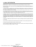
8.1 BEFORE TURNING THE POWER "ON":
1.
Check that all modules are installed in the proper location with the proper connections.
2.
Check all field (external) wiring for opens, shorts, and ground.
3.
Check that all interconnection cables are secure, and that all connectors are plugged-in properly.
4.
Check all Jumpers and Switches for proper setting.
5.
Check the AC power wiring for proper connection.
6.
Check that the chassis is connected to
EARTH GROUND
(cold water pipe).
7.
Make sure to close and secure the front cover plate before powering the system from main AC supply.
8.
To prevent sparking, connect the main AC power supply first. Then connect the batteries.
DO NOT CONNECT THE BATTERIES FIRST.
Follow the power-up procedure.
8.2 POWER-UP PROCEDURE:
1.
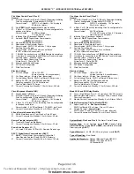
After completing the System Checkout procedures, power-up the panel. The "AC-ON" green LED should
illuminate, the “Common Trouble” LED should illuminate, and the buzzer should sound. Press the “System
Reset” button.
2.
Since the batteries are not connected, the "Battery Trouble" LED should illuminate, and the buzzer should sound
intermittently and the Common Trouble LED should flash.
3.
Connect the batteries. Observe correct polarity. The red wire is positive (+) and black wire is negative (-).
4.
All indicators should extinguish except for normal power "AC-ON" green LED.
5.
Configure the Fire Alarm Control Panel as described in the Configuration section.
8.3 TROUBLESHOOTING:
Circuit Trouble
Normally when a Circuit trouble occurs, its designated trouble indicator will be
illuminated
,
as well as the Common Trouble Indicator and the Buzzer. To correct the fault, check for
open wiring on that particular Circuit loop or if the Circuit Disconnect Switch is on.
Please
note: Disconnecting a Circuit will cause a system trouble (off-normal position).
Remote Fail
A
Remote Trouble
will be indicated on the main panel display for any failure reported by,
or failure to communicate with an
RA8
Remote Annunciator,
DACT
, or
PRM
.
Ground Fault
This panel has a common ground fault detector. To correct the fault, check for any external
wiring touching the chassis or other Earth Ground connection.
Battery Trouble
Check for the presence of batteries and their conditions. Low voltage (below 20.4V) will
cause a battery trouble. If battery trouble condition persists, replace batteries promptly.
Technical Manuals Online! - http://www.tech-man.com
firealarmresources.com

