


Gamatronic Electronic Industries Ltd.
POWER+
SA
User Guide, Release 1.6
33
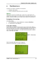
7.
F
IRST
-T
IME
S
ETUP
Your
POWER+ SA
UPS is capable of operating with any of three possible line
configurations. The configuration used by the UPS depends on the AC input
supplied and on the UPS settings.
The permitted line configurations are shown in the following table.
I
I
N
N
P
P
U
U
T
T
O
O
U
U
T
T
P
P
U
U
T
T
S
S
H
H
O
O
R
R
T
T
H
H
A
A
N
N
D
D
D
D
E
E
S
S
I
I
G
G
N
N
A
A
T
T
I
I
O
O
N
N
3
3
P
P
H
H
A
A
S
S
E
E
S
S
,
,
4
4
0
0
0
0
V
V
E
E
A
A
.
.
3
3
P
P
H
H
A
A
S
S
E
E
S
S
,
,
4
4
0
0
0
0
V
V
E
E
A
A
.
.
3
3
-
-
3
3
3
3
P
P
H
H
A
A
S
S
E
E
S
S
,
,
4
4
0
0
0
0
V
V
E
E
A
A
.
.
1
1
P
P
H
H
A
A
S
S
E
E
O
O
F
F
2
2
3
3
0
0
V
V
3
3
-
-
1
1
1
1
P
P
H
H
A
A
S
S
E
E
O
O
F
F
2
2
3
3
0
0
V
V
1
1
P
P
H
H
A
A
S
S
E
E
O
O
F
F
2
2
3
3
0
0
V
V
1
1
-
-
1
1
Your
POWER+ SA
UPS was probably already set at the factory or by your dealer to
operate with the number of input and output phases appropriate for your
requirements.
The cable connections for your
POWER+ SA
UPS vary depending on which line
configuration is used. Refer to the appropriate section below.
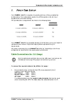
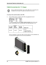
Cable Connections for 3-3 Usage
Only an authorized electrician may wire the UPS power connections. Do
not attempt to wire any of the power connections on your own.
To connect the required cables to the UPS for 3-3 usage:
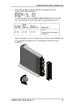
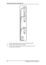
1.
Ensure that the lines coming into the UPS are equipped with circuit
breakers of the following capacity:
UPS output:
3x20A Class C
Bypass output:
3x20A Class
C
AC input:
3x20A Class C
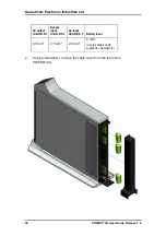
The following table gives the
required cable diameters
that must be used
when connecting the UPS. The table states the cable diameters in mm
2
.


