


G
AMATRONIC
E
LECTRONIC
I
NDUSTRIES
L
TD
.
14
CENTRIC 3x480, User Guide, rel. 1.7
5.
C
ENTRIC CONTROL SYSTEM
The
Centric
control system provides the user complete control over the UPS and its operating parameters.
This chapter describes basic, most frequently-used functions.
5.1
The main screen (main menu)
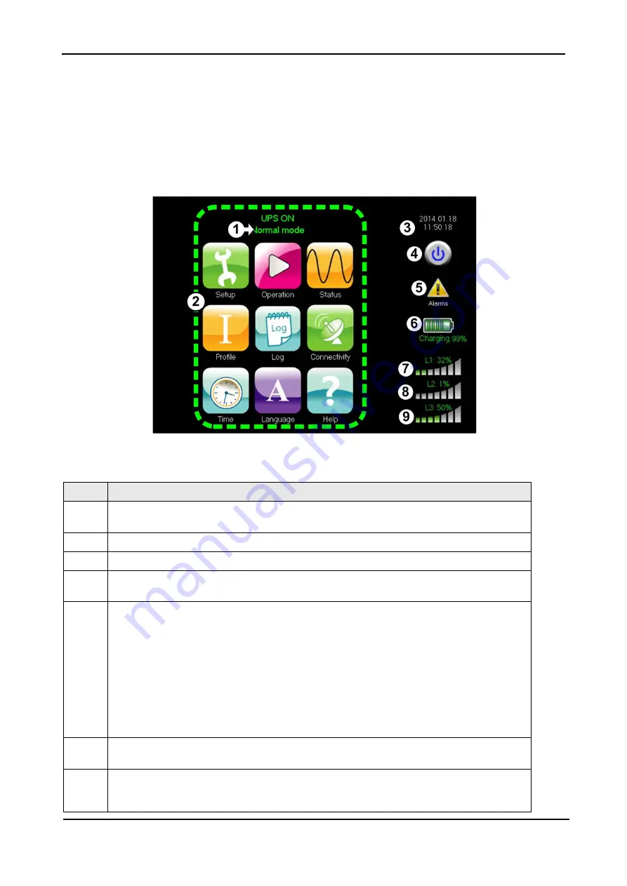
The main menu is the user's starting point for most operations. Figure 7 illustrates the main screen and
Table 4 explains the main screen's features.
Figure 7: The main screen and its features
Table 4: Features of the main screen
I
TEM
D
ESCRIPTION
1
The operational status (ON/OFF) and current mode
(Normal [inverter] mode / bypass mode / battery mode)
2
Menu options:
pressing these icons provide access to the main submenus.
3
Current date and time.
4
UPS soft on/off button:
Pressing this icon displays the UPS ON/OFF screen, which
enables the user to turn the UPS on and off.
5
Alarm indicator
(see
):
•
When there is one or more active alarms of “error” status (the most serious status),
a red circle with a white “x” inside is displayed.
•
When there is one or more active alarms of “warning” status (and no alarms of
“error” status), a yellow triangle with an exclamation point inside is displayed.
•
When there are informational messages but no messages of “error” or “warning”
status, an “I” in a blue circle is displayed
•
When there are no active alarms or informational messages, this area of the main
screen is blank. Pressing this icon displays the Active Alarm screen.
6
Battery indicator:
Indicates the status of the battery: charging or discharging.
Pressing on this icon displays the Battery Status screen.
7, 8, 9
Load indicators:
Indicates the approximate load level on each output phase. With no
load, all the vertical bars are white. As load increases, the vertical bars change color,
from left to right.


