


12
3.3 INSTALLAZIONE DELLE PARTI
SMONTATE.
La macchina viene fornita con in
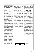
dotazione le lame affilate (A - Figura
4), con le quali si possono effettuare la
maggior parte delle lavorazioni. Esse
sono già correttamente posizionate
all'interno della vasca.
A richiesta, possono essere fornite
anche le lame dentate (B - Figura 4),
e/o le lame forate (C - Figura 4), per
eseguire lavorazioni più specifiche. In
questo caso, dette lame, si troveranno
all'esterno della macchina, racchiuse
nell'apposita scatola di protezione.
Per procedere alla sostituzione delle
lame, procedere come segue:
- Assicurarsi che la macchina sia
spenta, disinserendo l'interruttore
magnetotermico a muro e premendo il
pulsante di STOP/ARRESTO della
macchina stessa;
- Togliere il coperchio, facendolo
ruotare in senso antiorario (Figura 3);
- Adottare le opportune cautele,
indossando quanti morbidi ma con
buona presa, onde evitare un
accidentale contatto delle dita con le
lame affilate;
- Afferrare con una mano la parte
superiore del mozzo porta-lame,
quindi estrarlo con cautela;
- Riporre il mozzo estratto dalla
macchina, in posto sicuro, avendo ben
cura di proteggere le lame da
eventuali futuri contatti accidentali;
- Procedere all'inserimento del mozzo
porta-lame che necessita, avendo ben
cura che vada correttamente infilato
nell'albero motore e che, la lama
inferiore, sfiori il fondo senza toccarlo.
Nel caso che la predetta lama tocchi il
fondo, si rende necessario regolarne
l'altezza, procedendo nel modo
seguente:
- Nella parte superiore del mozzo
porta-lame, si trova una vite che
permette la regolazione dell'altezza
delle lame;
- Agendo su di essa, con un
cacciavite, in senso orario, si
provocherà un allontanamento delle
lame dal fondo della vasca; di
conseguenza, agendo su di essa in
senso antiorario, si provocherà un
avvicinamento delle lame al fondo
della vasca.
The base must rest on a solid, uniform
and properly levelled surface. The
machine requires no anchoring to the
supporting surface.
3 . 3 I N S T A L L A T I O N O F
DISASSEMBLED PARTS
The machine is supplied with the
cutter blades (A - fig.4) (sharpened),
with which the user can perform most
of the operations possible with this
machine. The blades are already
positioned correctly inside the tub.
On request, GAM can also supply
toothed blades (B - fig.4) and/or bored
blades (C - fig.4) for more specific use.
If supplied, these blades will be
delivered outside the machine and
packed in their own protective carton.
To replace the blades, proceed as
follows:
- Make sure the machine is switched
off, by disconnecting the thermo-
magnetic switch in the main power
circuit (on the wall) and pressing the
STOP button on the machine itself.
- Take off the cover by turning it in the
counter-clockwise direction (fig.3).
- Be very careful so that fingers do not
come into contact with the sharp
blades. Wear protective gloves during
this operation. These should be soft
and yet strong enough to allow the
user to grip the blades securely.
- With one hand take hold of the upper
part of the blade support hub and
remove carefully.
- Put the blade hub in a safe place and
cover the blades in some way so that
accidental contact is not possible.
- Insert the blade hub required, making
sure it is correctly positioned on the
motor shaft and that the lower blade
rests at a minimum distance from the
bottom surface of the tub without
actually touching it.
If this blade touches the bottom of the
tub, its height must be adjusted. To
adjust the blade height proceed as
follows:
- In the upper part of the blade support
hub there is a screw which allows for
height adjustment.
- Use a screwdriver to turn this screw
(clockwise direction) and distance the
blades from the bottom of the tub. If
the screw is turned in the opposite
direction (counter-clockwise), the
blades will move closer to the bottom.
Schneideinsatz (A- Abb.4) geliefert,
mit dem die meisten Bearbeitungen
durchgeführt werden können. Dieser
Einsatz ist bereits korrekt im
Wanneninneren motniert.
Auf Wunsch kann auch ein Einsatz mit
gezahnten Schneiden (B - Abb.4) und/
oder ein gelochter Einsatz (C - Abb.4)
für spezifische Bearbeitungen geliefert
werden. In diesem Fall werden diese
Einsätze separat in einer Schachtel
verpackt mit der Maschine geliefert.
Auswechseln der Einsätze:
- Maschine ausschalten (den
thermomagnetischen Schalter an der
Wand ausschalten und die STOPtaste
der Maschine drücken).
- D e n D e c k e l g e g e n d e n
Uhrzeigersinn drehen und abnehmen
(Abb. 3).
- Weiche Handschuhe, die ein gutes
Zugreifen gestatten, anziehen, um die
Hände zu schützen.
- Mit einer Hand den oberen Teil der
Einsatznabe anfassen und vorsichtig
herausziehen.
- Den Einsatz an einem sicheren Platz
ablegen und die Schneidmesser
entsprechend schützen.
- Den gewünschten Einsatz vorsichtig
in die Motorwelle einsetzen; die untere
Klinge darf den Boden nicht berühren,
muß sich jedoch unmittelbar über
diesem befinden.
Berührt die Klinge den Boden, ist ihre
Höhe wie folgt zu justieren:
- Am oberen Teil der Nabe befindet
sich eine Schraube zum Einstellen der
Schneidmesserhöhe.
Mit einem Schraubendreher im
Uhrzeigersinn drehen, bis die Klingen
weit genug vom Wannenboden
entfernt sind. Dreht man gegen den
U h r z e i g e r s i n n , w e r d e n d i e
Schneidmesser wieder zum Boden hin
verstellt.
A B C
Figura 4
Abb. 4
Figura 3
Abb. 3