Galmet KW-10 Operation And Installation Manual, Warranty Card Download Page 15

15 


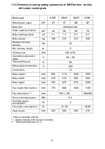
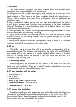
3.2 Setting up the boiler 

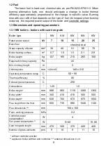
The boiler does not require a foundation. The boiler should be placed in 

a  way  that  allows  access  for  proper  maintenance  (cleaning  the  boiler  - 
access to the top and bottom {for KWRU boilers} cleaning hatch). 

Installation  of  the  boiler  should  be  performed  in  accordance  with  PN-

87/B-024411.  The  room  where  the  boiler  is  to  be  situated  should  have  at 
least  two  140x140mm  vents  (gravitational  ventilation),  with  one  situated 
150mm  above  floor  level  and  the  other  near  the  ceiling.  The  boiler  room 
doors  should  open  to  the  outside  and  be  made  of  fireproof  materials.  The 
room should be dry with a sewer grate installed in the floor, water supply and 
an earthed electrical installation. 

Lighting for the front side of the boiler is to be provided.  
The  socket  for  connecting  the  controller  should  have  a  safety  contact 

and be placed at a safe distance from sources of heat and water. 

The  boiler  should  be  placed  in  the  boiler  room,  so  that it  is  away  from 

easily flammable items, fuel should be fenced off. 


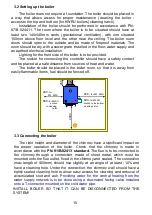
3.3 Connecting the boiler 

The right height and diameter of the chimney have a significant impact on 

the  proper  operation  of  the  boiler.  Check  that  the  chimney  is  made  in 
accordance with the

 PN-91/B-02413 standard. 

The flue is to be connected to 

the  chimney  through  a  connection  made  of  sheet  metal,  which  must  be 
mounted onto the flue outlet, fixed in the chimney and sealed. The connection 
(max  length  of  400mm)  should  rise  slightly  at  an  angle  of  at  least  -10%  and 
have a cleaning hole. Under the connection, the chimney  wall should have  a 
tightly sealed cleaning hole to allow  easy access for cleaning and removal of 
accumulated  soot  and  ash. 

Providing  water  for  the  central  heating  from  the 

water  supply  network  is  to  be  done  using  a  downward  facing  valve  installed 
onto a T-connector mounted on the cold water pipe.


  INSTALL  BOILER  SO  THAT  IT  CAN  BE  DISCONNECTED  FROM  THE 

SYSTEM! 


2000


200


200 - 

for KW, KWR


600 -

for KWRU 

access to the bottom 
cleaning hatch 

200 -

 for  

         KW, KWR


600 -

for KWRU 

             access    
      to cleaning     
                hatch 


Summary of Contents for KW-10

Page 1: ...post pl tel 796 067 784 Operation and installation manual Warranty Card Please read the instructions before installation and use of the product Water boiler for central heating GT kW with cast iron grate with water cooled grate standard version with draught regulator with fan and controller Controller Fan LX EKO pid MM LX EKO pid 2 EW ST 32 pid ...

Page 2: ...2 www galmet com pl ...

Page 3: ...3 ...

Page 4: ...4 ...

Page 5: ...5 ...

Page 6: ...lating Panels 13 2 6 Tools supplied with the boiler 13 3 BOILER INSTALLATION 13 3 1 Transporting the boiler 13 3 2 Setting up the boiler 14 3 3 Connecting the boiler 14 3 4 Central heating installation diagram 16 4 BOILER USE AND MAINTENANCE 17 4 1 Lighting the boiler 17 4 2 Adding fuel 18 4 3 Stopping boiler operation 18 4 4 Cleaning the boiler 18 5 CONDITIONS FOR SAFE USE OF THE BOILER 19 6 IMPR...

Page 7: ...with a high calorific value and adequate granulation is used 1 1 Application Steel boilers of the GT KW GT KWR GT KWRU GT KWRUZ types are intended for heating single family houses equipped with hydronic central heating of an open type system with gravitational or forced circulation The system within which the boiler operates must be equipped with safety features in accordance with the requirements...

Page 8: ... boiler dm 3 30 40 51 66 76 Boiler heating surface m 2 0 7 1 0 1 5 2 1 2 6 Boiler weight kg 127 165 210 265 300 Required chimney capacity Pa 22 Min chimney height m 5 Chimney size mm 140x140 140 x 210 Operating temperature range C 50 90 Thermal efficiency 80 Exhaust gas temperature C 250 Connections 1 25 1 5 Boiler height mm 880 960 1110 1260 1360 Boiler width mm 340 410 410 500 500 Boiler depth m...

Page 9: ...t m 5 Chimney size mm 140 x 210 Operating temperature range C 50 90 Thermal efficiency 80 Exhaust gas temperature C 250 Connections 1 5 Boiler height mm 960 1110 1260 1360 Boiler width mm 410 410 500 500 Boiler depth mm 760 870 870 1000 Flue height from the floor mm 735 880 1040 1140 Flue dimensions mm 150 x 150 180x180 Perm working pressure MPa 0 2 Controller power consumption W 4 Fan power consu...

Page 10: ...fficiency 80 Exhaust gas temperature C 250 Connections 1 5 1 5 2 2 5 2 5 3 Boiler height mm 1120 1220 1390 1480 1540 1550 Boiler width mm 465 580 650 750 750 910 Boiler depth mm 980 1190 1340 1560 1590 2050 Flue height from the floor mm 885 1025 1070 1260 1290 1230 Flue dimensions mm 150x150 180x180 200x200 250x250 250x250 300x300 Perm working pressure MPa 0 2 Controller power consumption W 4 Fan ...

Page 11: ...lls and into the water With these boilers it is possible to achieve combustion from the bottom by ignition from the top through the fuel loading hatch The air from the fan passes over the cold fuel and only the upper part of it burns The boiler s power output is reduced by the area of the chamber walls occupied by the cold fuel Fuel burns gradually allowing for stable control over the power output...

Page 12: ...E A B C D E F H I J L M R KW 7 470 340 650 630 170 410 880 110 150 200 160 270 KW 10 550 410 735 750 180 480 960 150 150 260 170 320 KW 15 660 410 880 870 200 600 1110 160 150 260 200 370 KW 20 660 450 1050 870 250 600 1260 170 150 310 240 420 KW 25 670 500 1140 1000 250 600 1360 180 180 360 240 420 KWR 11 550 410 735 750 180 480 960 150 150 260 170 320 KWR 17 660 410 880 870 200 600 1110 160 150 ...

Page 13: ...9 Air flap 10 Grate hatch 11 Flue with damper 12 Boiler insulation 13 Cold water connection 14 Hot water connection 15 Thermometer 16 Regulator 17 Controller 18 Fan 19 Secondary air inlet 20 Lower combustion flap 21 Smoke closure 22 Bottom cleaning hatch 23 Top cleaning hatch for KWRUd type boiler not used in KWRUz type boilers BOILER TYPE A B C D E F H I J L M R KWRuz22 760 465 885 980 250 695 11...

Page 14: ...nual air intake flap operated using a screw or a controller mounted on the 3 4 connection on the boiler body 2 4 Flue The boiler has a welded flue with a rectangular cross section with an adjustable damper The flue can be screwed into the boiler with four M10 bolts and sealed with a cord gasket or it can be welded At the bottom of the flue there is a cleaning hatch for removal of ash and soot from...

Page 15: ...hould be placed in the boiler room so that it is away from easily flammable items fuel should be fenced off 3 3 Connecting the boiler The right height and diameter of the chimney have a significant impact on the proper operation of the boiler Check that the chimney is made in accordance with the PN 91 B 02413 standard The flue is to be connected to the chimney through a connection made of sheet me...

Page 16: ...alled in closed central heating systems provided that a DBV or JBV cooling valve is installed and water from the mains is provided in a continuous uninterrupted manner In accordance with safety regulations and the instruction manual for DBV JBV valves their proper operation should be verified each day by turning the knob Installation of cooling coil and cooling valve on the boiler option Cooling c...

Page 17: ... 07 06 fan 5 Adjustment screw for fan flap 6 Boiler overheat sensor 7 Boiler temperature sensor 8 DHW temperature sensor 9 Differential valve 10 Central heating pump 11 DHW pump 12 Expansion vessel 13 Overflow and bleed pipe 14 Indicator tube 15 Indicator tube valve 16 Drain valve 17 Sewage grille 18 Exhaust gas sensor optional ...

Page 18: ...wer output and fuel type Up to 20kW maximum fan power is 20 Select an appropriate blow off for the burning process to last as long as possible and maintain the desired temperature If a large volume of burning embers is present in the firebox setting a lower temperature in the controller will not reduce the temperature immediately the fan will be turned off until the boiler cools down Until then co...

Page 19: ...ilation boiler room door open For the summer period when the boiler is not in use clean the boiler firebox heat exchanger channels tubes of soot and ash In addition open all hatches After the summer break period test circulation pumps mounted in the system and the fan before starting the boiler 4 4 Cleaning the boiler The boiler must be cleaned in order to ensure good heat exchange with the heat e...

Page 20: ...onnected with the maintenance of the boiler should be kept there Take care of the boiler frequent cleaning ensuring hatches are tightly closed on the boiler flue and chimney and the connected water system In systems with forced circulation use a gravity by pass with a differential valve This ensures that in case of power failure the hot water from the boiler can flow to the radiators and cool down...

Page 21: ...crease single fuel portion FUEL DOES NOT BURN COMPLETEL Y bad air adjustment insufficient chimney draught increase the amount of air choose blow off time and power check chimney size and flue SLAG FORMS too high temp of burning too low temperature of coal ash melting reduce the amount of air change fuel EXHAUST GAS OUTFLOW FROM BOILER dirty heat exchanger channels tubes closed flue damper gaskets ...

Page 22: ...te security and maintenance Repairs performed during the warranty period by unauthorized persons damage caused by failure to follow instructions 5 Claims regarding the quality of the boiler should be reported to the manufacturer by sending a completed claim coupon filled out by the point of sale 6 If the claim proves to be unjustified the costs associated with the arrival of a representative are t...

Page 23: ...23 ...

Page 24: ...nician Name and address of the owner User signature Repair date Description of repair Stamp and signature of the technician Name and address of the owner User signature Repair date Description of repair Stamp and signature of the technician Name and address of the owner User signature Date of commissioning Name of installer Installation description Installer s stamp Name and address of the owner U...

Page 25: ...oupon 2 WARRANTY CARD Date of sale Date of manufacture No of fan No of controller Serial No Boiler type technika grzewcza Warranty Coupon 3 Galmet Sp z o o Sp K 48 100 Głubczyce ul Raciborska 36 tel 48 77 40 34 500 fax 48 77 40 34 599 customer service 48 77 40 34 530 e mail serwis galmet com pl Date of sale Date of manufacture No of fan No of controller Serial No Boiler type technika grzewcza Noti...

Reviews: