FC66002179 – Rev.00
18
Instructions for installing Micronet
Connection to the RS485 communication network
The communication network relies on a simple shielded 2-conductor
cable, directly connected to the RS485 serial ports of the controllers
(terminals A, B and GND).
"Use AWG24 cable (diameter 0,5mm) to realize the
network"
WARNING:
To avoid any operation problems, the cables of
the communication bus (RS485) and the cables
of the of the probes cannot be installed next to
power cables (230V);
In the case of the ERGO “LARGE” solution the network terminates
on the RS232-RS485 converter, which must be connected to the
serial port of the personal computer in which the
ERGO
supervision
software resides. The network is powered by the converter itself.
The communication network must have the following general
structure:
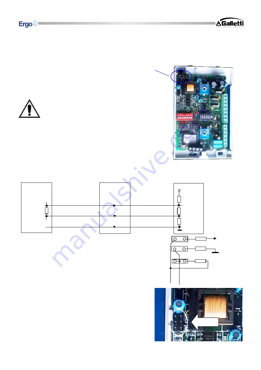
Pull-up, pull-down and termination resistors are already present inside
each MICRONET controller and may be activated via the jumpers
provided.
The certainty of logic levels is obtained with the pull-up and pull-
down resistors. These resistors are also present in the RS232 – RS485
serial converter supplied with the software.
In this case only the termination resistor, on the last Micronet in the
network, needs to be activated by means of J5
If the serial converter is not used (because a serial converter other
the one supplied is already present or because the SMALL solution
is being implemented), it is also necessary to activate resistors J3,
J4 and J5 (on the first controller) as well as the termination resistor
(J5) on the controller farthest from the Master or from the PC in
which the serial converter is installed.
Briefly, the situation is as follows:
B
A
+5 V
560
Ω
560
Ω
120
Ω
J3
J4
J5
560
Ω
120
Ω
560
Ω
120
Ω
B
A
+5
Micronet 1
Micronet K
Master
GND


