background image

 6


English

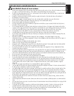
Important Informa  on

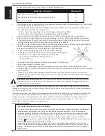
Minimum clearances from power lines for electric animal fences

Power line  Voltage V

Clearance ft

Less than or equal to 1 000

10

Greater than 1 000 and less than or equal to 33 000

13

Greater than 33 000

26

• If 

connec  ng leads and electric animal fence wires are installed near an overhead power line, their height 

above the ground shall not exceed 10  . 
This height applies either side of the orthogonal projec  on of the outermost conductors of the power 
line on the ground surface, for a distance of:-


-

6    for power lines opera  ng at a nominal voltage not exceeding 1000V;


-

50    for power lines opera  ng at a nominal voltage exceeding 1000V.

• 

Fence wiring should be installed well away from any telephone or telegraph line or radio aerial.

• 

Where an electric animal fence crosses a public pathway, a non-electri

fi

 ed gate shall be incorporated 

in the electric animal fence at that point or a crossing by means of s  les shall be provided. At any such 
crossing, the adjacent electri

fi

 ed wires shall carry warning signs (G6020).

• 

Any part of an electric animal fence that is installed along a public road or pathway shall be iden  

fi

 ed by 

electric fence warning signs (G6020) at regular intervals that are securely 
fastened to the fence posts or 

fi

 rmly clamped to the fence wires.

• 

The size of the warning sign shall be at least 4 inches x 8 inches.

• 

The background color of both sides of the warning sign shall be yellow. 
The inscrip  on on the sign shall be black and shall be either:


-

the substance of “CAUTION: Electric Fence” or,


-

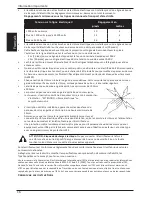
the symbol shown: 

• The 

inscrip  on shall be indelible, inscribed on both sides of the warning

sign and have a height of at least 1 inch.

• 

Ensure that all mains operated, ancillary equipment connected to the electric animal fence circuit 
provides a degree of isola  on between the fence circuit and the supply mains equivalent to that provided 
by the energizer.

• Protec  on from the weather shall be provided for the ancillary equipment unless this equipment is 

cer  

fi

 ied by the manufacturer as being suitable for use outdoors and is of a type with a minimum degree 

of protec  on IPX4.

WARNING: Risk of Electric Shock.

 Do not connect the energizer simultaneously to a fence and to any 

other device such as a ca  le trainer or a poultry trainer. Otherwise, lightning striking your fence will 
be conducted to all other devices.

This energizer complies with interna  onal safety regula  ons and is manufactured to interna  onal standards.
Gallagher reserves the right to make changes without no  ce to any product speci

fi

 ca  on to improve reliability, 

func  on or design. E & OE.

The author thanks the Interna  onal Electrotechnical Commission (IEC) for permission to reproduce Informa  on from 
its Interna  onal Publica  on 60335-2-76 ed.2.0 (2002). All such extracts are copyright of IEC, Geneva, Switzerland. 
All rights reserved. Further informa  on on the IEC is available from www.iec.ch. IEC has no responsibility for the 
placement and context in which the extracts and contents are reproduced by the author, nor is IEC in any way 
responsible for the other content or accuracy therein

Save these instruc  ons

SERVICE OF DOUBLE-INSULATED APPLIANCES

In a double-insulated controller, two systems of insula  on are provided instead of grounding.  No equipment 
grounding means is provided in the supply cord of a double-insulated controller, nor should a means for 
equipment grounding be added to the controller.  Servicing a double-insulated controller requires extreme 
care and knowledge of the system, and should be done only by quali

fi

 ed service personnel.  Replacement 

parts of a double insulated controller must be iden  cal to the parts they replace.   A double insulated 
controller is marked with the words “DOUBLE INSULATION” or “DOUBLE INSULATED”.  The symbol for double 
insula  on 


may also be marked on the appliance.

To reduce the risk of electric shock, this fence controller has a polarized plug (one blade is wider than the 
other).  This plug will 

fi

 t in a polarized outlet only one way.  If the plug does not 

fi

 t fully in the outlet, reverse 

the plug.  If it s  ll does not 

fi

 t, contact a quali

fi

 ed electrician to install the proper outlet.  Do not change the 

plug in any way.

Summary of Contents for M50

Page 1: ...FENCE ENERGIZER 110V Instructions Notice d installation Instrucciones ENG FRA ESP YardMaster The Rustler The Wrangler M20 M50 M100 Pasture Guard...

Page 2: ...ER Whilst every e ort has been made to ensure accuracy neither Gallagher Group Lim ed nor any employee of the company shall be liable on any ground whatsover to any party in respect of decisions or ac...

Page 3: ...tante 15 Comment fonc onne l lectrificateur 18 Guide d installa on en 5 tapes 19 Op ons d espacement des fils et des poteaux 23 Liste de contr le de la tension 24 Mat riel et ou ls 25 Espa ol Informac...

Page 4: ......

Page 5: ...the same energizer For any two separate electric animal fences each supplied from a separate energizer independently med the distance between the wires of the two electric animal fences shall be at le...

Page 6: ...pment is cer fiied by the manufacturer as being suitable for use outdoors and is of a type with a minimum degree of protec on IPX4 WARNING Risk of Electric Shock Do not connect the energizer simultane...

Page 7: ...reduce livestock control All livestock need me to learn to respect the fence It may take several days to train the livestock and the fence may require minor adjustments Livestock that are prone to ju...

Page 8: ...enter page as a drilling guide drill 2 x 5 32 holes A B b Fix the screws provided into the wall leaving the head of the screw about 1 8 out from the wall c Place the energizer over and slide down onto...

Page 9: ...Unscrew the green GROUND terminal on the energizer and insert the loop of wire between the washers c Screw the terminal closed ensuring the wire is firmly clamped 3 Lay out the cable down walls and ou...

Page 10: ...teways rather than overhead Do not use electric gates to get power across gateways Install Lead out Cable G6270 in a plas c pipe buried 12 deep Turn the ends of the pipe down to keep water out Connect...

Page 11: ...from one end of the cable Bend the end of the wire to form a loop Unscrew the red FENCE terminal and insert the loop of wire between the washers Screw the terminal closed ensuring the wire is firmly c...

Page 12: ...ve pulse carrying wire Symbol indicates a ground wire For wire and post spacings in dry areas with poor grounding condi ons see your Gallagher dealer All Hot Ground Return Wire Post spacing 60 85 ft 1...

Page 13: ...red FENCE terminal from the ground system to the green GROUND terminal at gates etc 2 Check the voltage on the fence every 100 Note if the voltage is dropping The closer to a short the lower the volta...

Page 14: ...out Switch G6076 Warning Sign G6020 Line Post Insulators HOT HOT HOT Strain Insulators G6791 or G6781 Joint Clamps G6030 Permanent Fence GREEN Ground Rod 351 Ground Clamp 352HD RED Line Post Line Post...

Page 15: ...p rant Une cl ture lectrique ne doit pas tre aliment e par deux lectrificateurs di rents ou par le circuit d une cl ture ind pendante branch e sur le m me lectrificateur Dans le cas de deux cl tures l...

Page 16: ...eau de mise en garde doit tre de couleur jaune recto verso L inscrip on doit tre de couleur noire et doit comporter L indica on ATTENTION cl ture lectrique ou Le symbole montr L inscrip on doit tre in...

Page 17: ...nnel qualifi Les pi ces de remplacement d un lectrificateur double isola on doivent tre iden ques aux pi ces d origine Un lectrificateur double isola on est marqu des mots DOUBLE ISOLATION DOUBLE INSU...

Page 18: ...aux peut n cessiter plusieurs jours et il se peut que des adapta ons mineures doivent tre apport es la cl ture Il peut tre di cile de garder l int rieur d une cl ture des animaux qui sont enclins saut...

Page 19: ......

Page 20: ...s trous de 2 x 4mm A et B l aide du gabarit repris dans les pages centrales Vissez les boulons livr s dans le mur et faites en sorte que leur t te d passe de 3 mm du mur Faites correspondre les trous...

Page 21: ...SMALL FENCE ENERGIZER 110V M20 YardMaster M50 The Rustler M100 The Wrangler Pasture Guard...

Page 22: ......

Page 23: ...t repris dans les pages centrales b Vissez les boulons livr s dans le mur et faites en sorte que leur t te d passe de 3 mm du mur c Faites correspondre les trous de l appareil et suspendez le tape 2 I...

Page 24: ...u fil afin d obtenir une boucle b D vissez la borne verte TERRE de l lectrificateur et ins rez la boucle de fil entre les rondelles c Resserrez la borne en s assurant que le fil est bien fix 3 Fixez l...

Page 25: ...res lectriques pour faire traverser le courant Installez plut t un c ble d alimenta on G6270 dans un tuyau de plas que 30 cm 12 po de profondeur Courbez les extr mit s du tuyau vers le bas pour viter...

Page 26: ...ble Pliez l extr mit du fil afin d obtenir une boucle D vissez la borne rouge CL TURE et ins rez la boucle de fil entre les rondelles Resserrez la borne en s assurant que le fil est bien fix Fixez l a...

Page 27: ...c condi ons de mise la terre pauvres consultez votre d taillant Gallagher Tous charg s Fil de retour la terre Espacement des poteaux 20 25m 60 85 pieds 300mm 12 300mm 12 300mm 12 900mm 36 300mm 12 300...

Page 28: ...URE du syst me de mise la terre la borne verte TERRE aux por ques etc 2 Contr lez le voltage sur la cl ture tous les 33 m V rifiez si la tension chute Plus vous vous rapprocherez du dysfonc onnement p...

Page 29: ...Isolateurs de poteau CHARG CHARG CHARG Isolateurs de coin G6791 or G6781 Joints de connexion G6030 Cl ture permanente VERT Tige de prise de terre 351 Collier de serrage 352HD ROUGE Poteau Isolateurs...

Page 30: ...os energizadores diferentes o por un circuito independiente del mismo energizador Para cada dos cercas el ctricos diferentes alimentadas por dos energizadores diferentes la distancia entre los alambre...

Page 31: ...xterior y es del po con un grado de protecci n m nima IPX4 ADVERTENCIA Riesgo de choque el ctrico No conecte el energizador simult neamente a una cerca y a cualquier otro disposi vo como por ejemplo u...

Page 32: ...ecesitan empo para aprender a respetar la cerca Puede llevar varios d as entrenar al animal y puede que la cerca necesite ajustes menores Los animales con tendencia a saltar pueden ser di ciles de con...

Page 33: ...32 agujeros A B b Asegurar los tornillos en la pared dejando la cabeza del tornillo 1 8 fuera de la pared c Poner el Energizador sobre los tornillos y bajarlo sobre los tornillos de montar b a Paso 2...

Page 34: ...un gancho o vuelta b Desatornille el terminal verde TIERRA del energizador y ponga el gancho del cable entre las arandelas c Atornille el terminal asegurando que el cable est firmemente sujeto 3 Ex en...

Page 35: ...le los terrenos accidentados pedregosos o escarpados Para una mejor funci n de la cerca el ctrica u lice varios alambres por lo menos tres alambres conectados en paralelo 2 Reparta el alambre inferior...

Page 36: ...o recubre de uno de los extremos del cable Doble el extremo del cable hasta formar un gancho Desatornille el terminal rojo CERCA y ponga el gancho que se ha formado con el cable entre las arandelas At...

Page 37: ...2 Ganado Lechero Ganado de Carne Todos vivos Alambre de retorno a tierra 18 18 18 18 Todos vivos Alambre de retorno a tierra 36 Distancia entre postes 60 85 pies 10 28 10 10 28 10 48 Distancia entre p...

Page 38: ...onexiones el ctricas son seguras por ejemplo de la cerca al terminal rojo CERCA del sistema de erra al terminal verde TIERRA a las puertas etc 2 Revise el voltaje de la cerca cada 33 m Vigile si el vo...

Page 39: ...ncia G6020 Aisladores para poste de l nea Vivo Vivo Vivo Aislador de tensi n Abrazadera de l nea Cercos Permanentes Varilla de erra Abrazadera a erra VERDE Poste de l nea Aisladores para poste de l ne...

Page 40: ...www gallagher com Gallagher Private Bag 3026 Hamilton New Zealand...

Reviews: