background image


171 

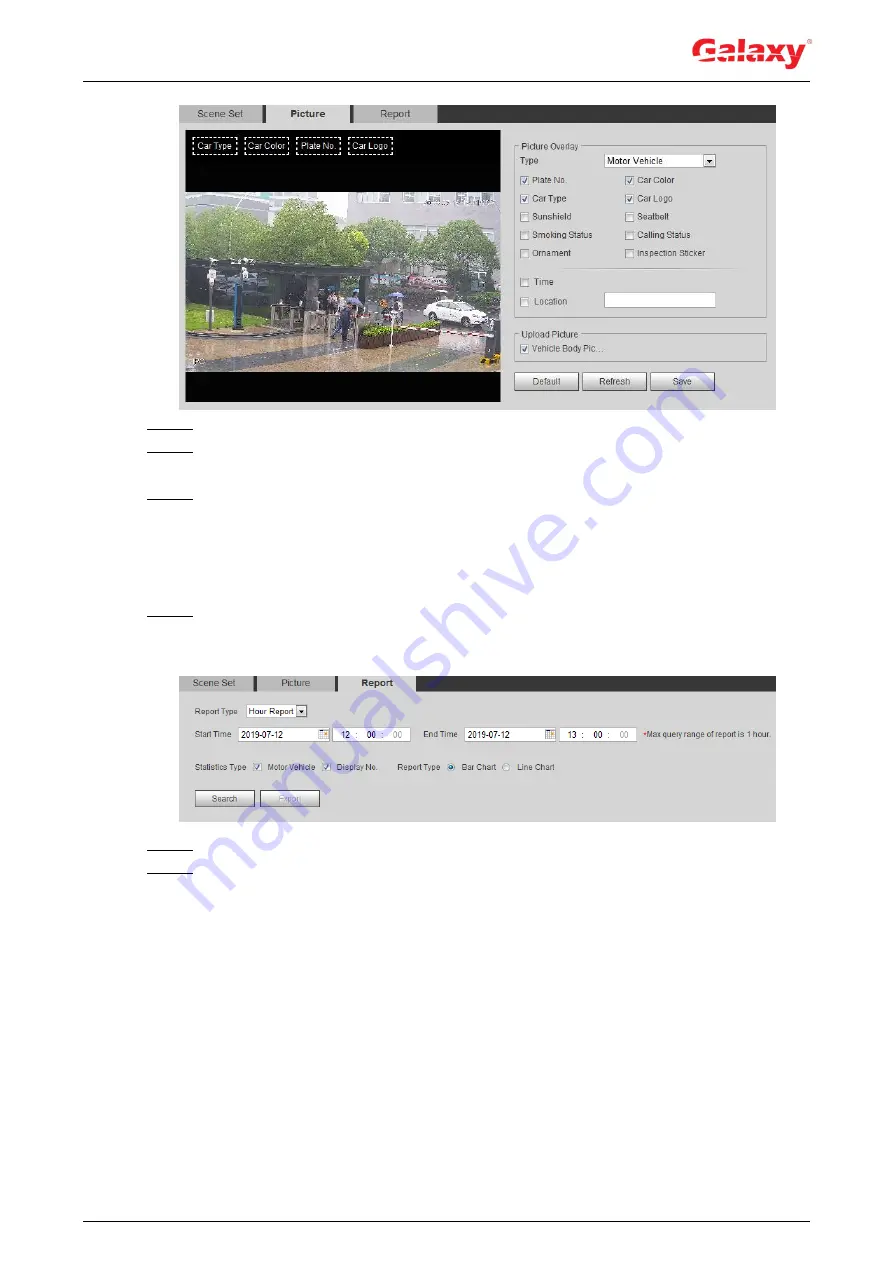
Figure 5-66 Picture (plate no. recognition) 


Step 2  Select 

Motor Vehicle

 from the 

Type

 drop-down list. 

Step 3  Set overlay information and box position,  such as plate no., time, car color, car type, 

and car logo. 

Step 4  Click 

Save

5.15.3 Viewing ANPR Report 

Generate data of ANPR in report form. 

Step 1  Select 

Setting > Event > ANPR > Report

The 

Report

 interface is displayed. See Figure 5-67. 

Figure 5-67 Report 


Step 2  Select the report type, start time, end time, and other parameters. 

Step 3  Click 

Search

The  statistical  results  are  displayed.  See  Figure  5-68.  Click 

Export

  to  export  the 

statistical report. 

Summary of Contents for Hunter Series

Page 1: ...Network Camera Web 3 0 Operation Manual V2 0 2 V1 0 0 ZHEJIANG DAHUA VISION TECHNOLOGY CO LTD ZHEJIANG DAHUA VISION TECHNOLOGY CO LTD Hunter Series Network Camera Web 3 0 Operation Manual V2 0 2...

Page 2: ...ement to the text Revision History Version Revision Content Release Date V2 0 2 1 Modified the contents of 5 15 Setting ANPR 2 Added modeling in 5 11 Face Detection December 2019 V2 0 1 Added 5 5 Sett...

Page 3: ...ten notice The product updates might cause some differences between the actual product and the manual Please contact the customer service for the latest program and supplementary documentation There s...

Page 4: ...l components Keep the indoor device away from rain or damp to avoid fire or lightning Keep sound ventilation to avoid heat accumulation Transport use and store the device within the range of allowed h...

Page 5: ...can also remove dust with an air blower Strengthen the protection of network device data and personal information by adopting measures which include but not limited to using strong password modifying...

Page 6: ...djustment Bar 12 4 3 PTZ Operation 19 4 3 1 Configuring External PTZ Protocol 19 4 3 2 Configuring PTZ Function 20 4 3 3 Calling PTZ 30 4 4 Playback 33 4 4 1 Playback Interface 33 4 4 2 Playing back V...

Page 7: ...4 5 4 3 Setting Scene Changing 125 5 5 Setting Smart Motion Detection 125 5 6 Setting Audio Detection 126 5 7 Setting Smart Plan 128 5 8 Setting IVS 128 5 8 1 Global Configuration 129 5 8 2 Rule Confi...

Page 8: ...ideo Structuralization Report 176 5 17 Setting Relay in 176 5 18 Setting Abnormality 177 5 18 1 Setting SD Card 177 5 18 2 Setting Network 178 5 18 3 Setting Illegal Access 179 5 18 4 Setting Voltage...

Page 9: ...ology IPC is connected to PC through network switch or router See Figure 1 1 Figure 1 1 General IPC network Get IP address by searching on ConfigTool and then you can start accessing IPC through netwo...

Page 10: ...s for smart track and enable alarm track Switch between smart track and speed dome auto track Video Detection Motion detection video tampering detection and scene changing detection When an alarm is t...

Page 11: ...stem performs linkages such as recording alarm output sending email PTZ operation and snapshot Face Recognition After detecting face make comparison between the detected face with the face in face dat...

Page 12: ...when an external alarm input device inputs alarm When an alarm is triggered the system performs linkages such as recording alarm output sending email PTZ operation and snapshot Abnormality SD card er...

Page 13: ...e first time 3 Device Initialization Basic parameters IP address Modify IP address according to network planning for the first use or during network adjustment 4 6 1 TCP IP Date time Set date and time...

Page 14: ...default Figure 3 1 Device initialization Step 2 Set the password for admin account For details see Table 3 1 Table 3 1 Description of password configuration Parameter Description User name The default...

Page 15: ...dates the system checks new version once a day automatically There will be system notice on Upgrade interface and Version interface if any new version is available Select Setting System Upgrade Online...

Page 16: ...the same network Follow the instruction to download and install the plug in for the first login Step 1 Open IE browser enter the IP address of the camera 192 168 1 108 by default in the address bar an...

Page 17: ...nterface The system will sleep automatically after idling for a period of time Figure 4 2 Live 4 2 Live This section introduces the layout of the interface and function configuration 4 2 1 Live Interf...

Page 18: ...resolution but also requires large bandwidth This option can be used for storage and monitoring For details see 4 5 2 1 Video Sub Stream It has small bit stream value and smooth image and requires les...

Page 19: ...iper of the camera Click the icon to enable or disable wiper function Ranging Click the icon select a point on the ground and the distance between the camera and the selected point will be displayed B...

Page 20: ...he configured storage path About viewing or configuring storage path see 4 5 2 5 Path Easy Focus Click the icon the AF Peak focus eigenvalue and AF Max max focus eigenvalue are displayed on the video...

Page 21: ...adjustment Adjusts the image saturation this value does not change image brightness Original Size Click the icon and then the video displays with original size Full Screen Click the icon to enter full...

Page 22: ...5 10 Setting Face Recognition For face detection see 5 11 Setting Face Detection ANPR Click the icon and the ANPR results are displayed on the Live interface For details see 5 15 Setting ANPR Video St...

Page 23: ...value The Speed is the adjustment range in one click The larger the value is the more the image would zoom in or out in one click 2 Click or hold button or drag the slider to adjust zoom Auto Focus Ad...

Page 24: ...mode to display images in stereo mode Figure 4 6 Fisheye Table 4 5 Description of fisheye configuration Parameter Description Installation mode Includes ceiling mount wall mount and ground mount Disp...

Page 25: ...2 Original image screen two independent sub screens Ground Mount does not support this display mode You can zoom or drag the image in all the screens You can rotate the image on the original image scr...

Page 26: ...adjust the vertical view 1P 8 180 rectangular panoramic image screen eight independent sub screens You can zoom or drag the image in all the screens You can drag the image in all the screens upper an...

Page 27: ...parameter configuration PTZ control and PTZ function configuration 4 3 1 Configuring External PTZ Protocol You need to configure PTZ protocol when accessing external PTZ otherwise the camera cannot co...

Page 28: ...Preset Step 2 Set the speed and click and to adjust the parameters of direction zoom focus and iris to move the camera to the position you need Step 3 Click Add to add the current position to be a pre...

Page 29: ...me to edit the name Step 3 Click Add to add preset Double click the duration to set the duration Step 4 Select the tour mode Original path The PTZ camera moves in the order of the selected presets Sho...

Page 30: ...o be the left limit 2 Click Set Right Limit to set the current position to be the right limit Step 4 Click Start to start scanning Click Stop to stop scanning 4 3 2 4 Pattern Pattern means a recording...

Page 31: ...nd iris according to the actual situation Step 4 Click Stop Rec to stop recording Step 5 Click Start to start patterning Click Stop to start patterning 4 3 2 5 Pan Enable Pan the camera can realize co...

Page 32: ...izontal rotation Click Stop to stop rotation 4 3 2 6 PTZ Speed PTZ speed means the rotation speed of the PTZ camera during touring pattern or auto tracking Step 1 Select Setting PTZ settings Function...

Page 33: ...ive any valid command within the set time Preparation You have configured the PTZ motions including preset scan tour or pattern Procedure Step 1 Select Setting PTZ settings Function Idle Motion The Id...

Page 34: ...is displayed See Figure 4 15 Figure 4 15 PowerUp Step 2 Select the Enable check box to enable the power up function Step 3 Select the power up motion When you select Auto the system will perform the...

Page 35: ...own line Step 3 Select the Enable check box to enable the PTZ limit function 4 3 2 10 Time Task After setting time task the camera performs the motions during the configured period Preparation You hav...

Page 36: ...me the time task automatically Step 6 Click Period setting to set the time of the task and then click Save For setting arm time see 5 1 1 1 Setting Period Step 7 Click Save Other Operations You can co...

Page 37: ...t to restart PTZ 4 3 2 12 Default Be careful when doing this operation It will restore the camera to default configuration and result in data loss Step 1 Select Setting PTZ settings Function Default T...

Page 38: ...default 4 3 3 Calling PTZ Click on Live interface and the PTZ configuration panel is displayed You can control PTZ and call PTZ function 4 3 3 1 PTZ Control You can rotate device zoom image and adjus...

Page 39: ...directions left right up down upper left upper right bottom left bottom right Click and draw a box in the image PTZ will rotate focus and quickly position the defined scene Rotate PTZ direction throug...

Page 40: ...the scan number and click Start the camera moves horizontally at a certain speed between the set left and right limit Click Stop to stop scanning Preset Set the preset number and click Go to the came...

Page 41: ...layback Before playing back video configure record time range record storage method record schedule and record control For details see 5 1 1 2 1 Setting Record Plan Before playing back picture configu...

Page 42: ...to the installation mode during playback This function is only available on fisheye cameras Rules Info Click intelligent rules and object detection box are displayed It is enabled by default Rules In...

Page 43: ...Record Snapshot Type Select the record type or snapshot type Record type includes General Event Alarm Manual Snapshot type includes General Event Alarm 6 Assistant You can zoom video image of the sele...

Page 44: ...from the Record Type drop down list and SD card from the Data Src drop down list See Figure 4 25 Select jpg from Record Type drop down list when playing back pictures and you do not need to select da...

Page 45: ...selected date in the order of time Click any point in the colored area on the progress bar See Figure 4 28 The playback starts from that moment Figure 4 28 Progress bar Click the video files of the s...

Page 46: ...rget video and then click See Figure 4 30 Figure 4 30 Clipping video Step 4 Click again on the progress bar to select the end time of the target video and then click Step 5 Click to download the video...

Page 47: ...elect dav from Record Type drop down list and SD card from the Data Src drop down list Select jpg from Record Type drop down list when playing back pictures and you do not need to select data source S...

Page 48: ...prevail 4 5 1 Conditions Configure camera parameters of the camera to ensure surveillance goes properly 4 5 1 1 Conditions Configure camera parameters according to the actual situation including pictu...

Page 49: ...nditions Figure 4 33 Camera conditions PTZ camera 4 5 1 1 2 Picture You can configure picture parameters as needed Step 1 Select Setting Camera Conditions Conditions Picture The Picture interface is d...

Page 50: ...he value is the more the contrast will be between bright and dark areas and the smaller the less If the value is set too big the dark area would be too dark and bright area easier to get overexposed T...

Page 51: ...nd improves the image clarity effectively solves the picture shaking problem Picture Freeze When you call a preset the image displays the preset location not the rotation image Step 3 Click Save 4 5 1...

Page 52: ...ured shutter range when auto adjusting according to the ambient lighting condition If the image brightness is not enough and the shutter value has reached upper or lower limit the system adjusts gain...

Page 53: ...r the result will be Step 3 Click Save 4 5 1 1 4 Backlight You can select backlight mode from Auto BLC WDR and HLS Step 1 Select Setting Camera Conditions Conditions Backlight The Backlight interface...

Page 54: ...in WB mode white objects would always display white color in different environments Step 1 Select Setting Camera Conditions Conditions WB The WB interface is displayed See Figure 4 37 Figure 4 37 WB...

Page 55: ...s color image Auto The system switches between color and black and white display according to the actual condition B W The system displays black and white image Sensitivity This configuration is avail...

Page 56: ...he camera will focus Calling preset positioning accurately or rotating PTZ also will trigger focus Manual Click or corresponding to Focus to adjust the focus Focus Limit When the focus length is too s...

Page 57: ...turns on the low beam lights first if the brightness is still not enough it turns on the high beam lights then When the ambient light turns brighter the system dims high beam lights until they are off...

Page 58: ...e actual condition Off Defog function is disabled Step 3 Click Save 4 5 1 1 10 Fisheye Select install mode and record mode according to the actual installation scene When the camera accesses to the pl...

Page 59: ...ns You can zoom or drag the image in all the screens 1O 3R Original image screen three independent sub screens You can zoom or drag the image in original image screen and move the image upper and lowe...

Page 60: ...ystem works under Day Night configuration Figure 4 46 Day Night Step 3 Click Save 4 5 1 3 Zoom and Focus You can adjust image clarity through auto or manual focus and adjust the image size through zoo...

Page 61: ...eck box to enable sub stream it is enabled by default You can enable multiple sub streams simultaneously Encode Mode Select encode mode H 264 Main profile encode mode Compared with H 264B it requires...

Page 62: ...e from CBR Constant Bit Rate The bit rate changes a little and keeps close to the defined bit rate value VBR Variable Bit Rate The bit rate changes as monitoring scene changes The Bit Rate Type can be...

Page 63: ...type image size quality and interval Step 1 Select Setting Camera Video Snapshot The Snapshot interface is displayed see Figure 4 48 Figure 4 48 Snapshot Step 2 Configure snapshot parameters For deta...

Page 64: ...ng You can enable this function when you need to protect privacy of some area on the video image Step 1 Select Setting Camera Video Overlay Privacy Masking The Privacy Masking interface is displayed S...

Page 65: ...er You can drag four rectangles at most Click Remove All to delete all the area boxes select one box and then click Delete or right click to delete it 2 Adjust the size of the rectangle to protect the...

Page 66: ...the Week Display check box Step 4 Move the time box to the position you want in the image Step 5 Click Save 4 5 2 3 4 Configure Text Overlay You can enable this function if you need to display text in...

Page 67: ...the text box to the position you want in the image Step 4 Click Save 4 5 2 3 5 Configure Font Attribute You can enable this function if you need to adjust the font size in the video image Step 1 Sele...

Page 68: ...4 55 Figure 4 55 Picture overlay Step 2 Select the Enable check box click Upload Picture and then select the picture to be overlaid The picture is displayed on the video image Step 3 Move the overlaid...

Page 69: ...custom box to the position you want in the image Step 4 Click Save 4 5 2 3 8 Configuring OSD Info You can enable this function if you want to display the information of preset PTZ coordinates zoom tou...

Page 70: ...which means 12x zoom rate North Select Enable and the north direction is displayed in the image RS485 Select Enable and it will enable RS 485 communication function Text Select Enable and set text and...

Page 71: ...tistics When the overlay function enabled during intelligent rules configuration this function is enabled simultaneously Step 1 Select Setting Camera Video Overlay Structured Statistics The Structured...

Page 72: ...erface is displayed See Figure 4 60 Figure 4 60 Ranging Step 2 Select the Enable check box and then set the installation height and time display Time display The display time of the ranging informatio...

Page 73: ...face statistics information When the overlay function enabled during intelligent rules configuration this function is enabled simultaneously Step 1 Select Setting Camera Video Overlay Face Statistics...

Page 74: ...the image and then configure the image quality of ROI You can draw four area boxes at most The higher the image quality value is the better the quality will be Click Remove All to delete all the area...

Page 75: ...LiveRecord Playback Snapshot The snapshot of playback interface The default path is C Users admin WebDownload PlaybackSnapshot Playback Download The downloaded video of playback interface The default...

Page 76: ...o both audio and intercom The default value is recommended Sampling Frequency Sampling number per second The higher the sampling frequency is the more the sample in a second will be and the more accua...

Page 77: ...re 4 66 Alarm audio Step 2 Click Add Audio File The Add Audio File dialog box is displayed See Figure 4 67 Figure 4 67 Add audio file Step 3 Configure the audio file Select Record enter the audio name...

Page 78: ...22 Description of TCP IP parameters Parameter Description Host Name Enter the host name and the maximum length is 15 characters Ethernet Card Select the Ethernet card that need to be configured and th...

Page 79: ...minutes to configure the device IP address by a ping packet with certain length the server will be turned off in 2 minutes or it will be turned off immediately after the IP address is successfully con...

Page 80: ...776 37780 37880 39999 42323 are occupied for specific uses Do not use the same value of any other port during port configuration Table 4 23 Description of port parameters Parameter Description Max Con...

Page 81: ...1 For example if you are using channel 2 then the channel 2 Subtype The bit stream type 0 means main stream Subtype 0 and 1 means sub stream Subtype 1 Example If you require the sub stream of channel...

Page 82: ...success prompt box is displayed and then the real time WAN IP address is displayed You can visit camera through the IP address 4 6 4 DDNS Properly configure DDNS and then the domain name on the DNS s...

Page 83: ...o check whether the domain name registration is successful Username Enter the user name and password that you got from the DDNS server provider You need to register an account includes user name and p...

Page 84: ...hentication from None SSL and TLS For details see Table 4 26 Title Enter maximum 63 characters in Chinese English and Arabic numerals Click to select title type including Name Device ID and Event Type...

Page 85: ...e 25 126 smtp 126 com none 25 Enable SMTP service in your mailbox Step 3 Click Save Step 4 Click Test to test whether the emails can be sent and received successfully 4 6 6 UPnP UPnP Universal Plug an...

Page 86: ...external port number and then you can visit the local area device with corresponding port 4 6 7 SNMP SNMP Simple Network Management Protocol which can be used to enable software such as MIB Builder a...

Page 87: ...kage and V3 is recommended In Trap Address enter the IP address of the PC that has MIB Builder and MG SOFT MIB Browser installed and leave other parameters to the default Table 4 27 Description of SNM...

Page 88: ...B Builder or MG SOFT MIB Browser Step 1 Run MIB Builder and MG SOFT MIB Browser Step 2 Compile the two MIB files with MIB Builder Step 3 Load the generated modules with MG SOFT MIB Browser Step 4 Ente...

Page 89: ...ameras with Bonjour enabled in the LAN Step 3 Click the camera to visit the corresponding web interface 4 6 9 Multicast When multiple users are previewing the device video image simultaneously through...

Page 90: ...1 Select Setting Network 802 1x The 802 1x interface is displayed See Figure 4 78 Figure 4 78 802 1x Step 2 Select the Enable check box and then configure parameters For details see Table 4 29 Table 4...

Page 91: ...ority of the data packets that used for configure or checking Step 3 Click Save 4 6 12 Access Platform 4 6 12 1 P2P P2P is a private network traversal technology which enables user to manage devices e...

Page 92: ...NVIF authentication is On by default which allows the network video products including video recording device and other recording devices from other manufacturers to connect to your device ONVIF is en...

Page 93: ...ting Non custom you need to enter server IP address and port IP address Support IPv4 or domain name Port We recommend that you use the default one Port Custom Address When selecting Custom you need to...

Page 94: ...is selected in the holiday schedule the system takes snapshot or records video as holiday schedule defined Preparation Set the record mode to be Auto in Record Control For details see 5 1 1 2 1 Setti...

Page 95: ...ction and Alarm Local Save in the internal SD card FTP Save in the FTP server NAS Save in the NAS network attached storage Step 3 Click Save Step 4 Configure other path parameters on Destination FTP o...

Page 96: ...alth status is excellent Blue The health status is good Orange The health status is moderate Red The health status is poor and you need to replace the SD card Select Setting Storage Destination Local...

Page 97: ...ssword The password to log in to the FTP server Remote Directory The destination path in the FTP server Emergency Local Select Emergency Local and when the FTP server does not work all the files are s...

Page 98: ...ter them as needed Password Remote Directory The destination path in the NAS server Step 4 Click Save 4 8 System This section introduces system configurations including general date time account safet...

Page 99: ...te Time interface is displayed See Figure 4 89 Figure 4 89 Date and time Step 2 Configure date and time parameters For details see Table 4 36 Table 4 36 Description of date and time parameters Paramet...

Page 100: ...ve the camera otherwise the spplicing might fail Step 1 Select Setting System General Splicing The Splicing inteface is dispalyed See Figure 4 90 and Figure 4 91 Figure 4 90 Splicing 1 Figure 4 91 Spl...

Page 101: ...must consist of 8 to 32 non blank characters and contain at least two types of characters among upper case lower case number and special character excluding You can have 18 users and 8 groups at most...

Page 102: ...94 Figure 4 92 Username Step 2 Click Add User The Add User interface is displayed See Figure 4 93 and Figure 4 94 Figure 4 93 Add user operation permission...

Page 103: ...er password and confirm it again The password must consist of 8 to 32 non blank characters and contain at least two types of characters among upper case lower case number and special character excludi...

Page 104: ...Enter the start address and end address of the host to be added 2 Select Validity Period Set the begin time and end time 3 Select Time Range Set the time range that allow user to log in For details s...

Page 105: ...ame and memo and then select group authorities Step 4 Click Save to finish configuration The newly added group displays in the group name list After adding group click to modify group memo or authorit...

Page 106: ...tails see Table 4 38 Table 4 38 Description of user parameters 2 Parameter Description Username User s unique identification You cannot use existed user name Password Enter password and confirm it aga...

Page 107: ...ce network and data security Step 1 Select Setting System Safety System Service The System Service interface is displayed See Figure 4 99 Figure 4 99 System service Step 2 Enable the system service ac...

Page 108: ...function and then the system would send the snapshot that was taken when alarm is triggered to your phone this is enabled by default Step 3 Click Save 4 8 5 2 HTTPS Create certificate or upload the a...

Page 109: ...P or Domain name must be the same as the IP or domain name of the device 4 Click Install See Figure 4 102 Figure 4 102 Certificate installation 5 Click Download to download root certificate 6 Click Do...

Page 110: ...wnload 7 Click Open The Certificate Information interface is displayed See Figure 4 104 Figure 4 104 Certificate information 8 Click Install Certificate 9 The Certificate Import Wizard interface is di...

Page 111: ...izard 10 Click Next The Certificate Store interface is displayed See Figure 4 106 Figure 4 106 Certificate import wizard 11 Select the storage location and click Next The Certificate Import Wizard int...

Page 112: ...ted list can you access the camera Ports are the same Banned list When the IP MAC of your PC is in the banned list you cannot access the camera Ports are the same PING prohibited Enable PING prohibite...

Page 113: ...ork Access from Rule Type list and then select the Enable check box Enable PING prohibited and Prevent Semijoin and click Save You do not need to configure parameters Enable Network Access and configu...

Page 114: ...When selecting BannedList in Mode and All IP Address in Rule Type you cannot select the Device All Ports check box Device start server port and Device end server port Set Device start server port and...

Page 115: ...k Save 4 8 6 2 External Light You need to configure external light mode when the external light is used Preparation Connect external light with RS 485 port You have configured serial port parameters F...

Page 116: ...automatically Light Brightness Set the brightness of the external light Step 3 Click Save 4 8 6 3 Wiper Step 1 Select Setting System Peripheral Wiper The Wiper interface is displayed See Figure 4 113...

Page 117: ...109 Parameter Description wiper will work as the set time Click Once and the wiper works once It can be used to check whether the wiper can work normally Step 3 Click Save...

Page 118: ...Setting Alarm Linkage 5 1 1 Alarm Linkage When configuring alarm events select alarm linkages such as record snapshot See Figure 5 1 When the corresponding alarm is triggered in the configured arming...

Page 119: ...iple days at one time You can set 6 time periods per day Step 3 Click Save 5 1 1 2 Record Linkage The system can link record channel when an alarm event occurs After alarm the system stops recording a...

Page 120: ...for normal record on the timeline Method two Enter an actual time period 1 Click Setting next to a day The Setting interface is displayed See Figure 5 4 Figure 5 4 Setting record time period 2 Select...

Page 121: ...saves the video data within the pre event record time to the video file Disk Full Recording strategy when the disk is full Stop Stop recording when the disk is full Overwrite Cyclically overwrite the...

Page 122: ...Schedule Snapshot The Snapshot interface is displayed See Figure 5 1 Figure 5 1 Snapshot Step 2 Select snapshot type and set time period Green represents normal snapshot plan such as timing snapshot y...

Page 123: ...e When an alarm is triggered the system can automatically link with relay out device On the alarm event setting interface such as the motion detection interface select Alarm and set Alarm Delay When a...

Page 124: ...ter an extended time of period after an alarm It is 5 seconds 30 seconds Period The period for using white light When an alarm triggered during the configured period the system links white light For t...

Page 125: ...consecutive login password error is up to the allowable number Illegal access detection is enabled For details see 5 18 3 Setting Illegal Audio Detection The alarm is triggered when there is audio co...

Page 126: ...rface is displayed the corresponding alarm information is displayed in the alarm list at the right side of the Alarm interface Select Play Alarm Tone and select the tone path The system would play the...

Page 127: ...o image of the speed dome to a position aligned with the panoramic image and then click Calibration box is displayed in the images of speed dome and panoramic camera 2 Drag the calibration box to a pr...

Page 128: ...re an object disappears The speed dome would automatically links to a corresponding position and tracks an object until the object moves out of the monitoring range when the intelligent rules of the p...

Page 129: ...xample Step 1 Select Setting Event Panoramic Calibration The Panoramic Calibration interface is displayed See Figure 5 13 Figure 5 13 Panoramic calibration Step 2 Select channel 2 and then select a ca...

Page 130: ...ny considerable change on the video such as moving object fuzzy image the system performs an alarm linkage 5 4 1 Setting Motion Detection The system performs an alarm linkage when the moving object ap...

Page 131: ...ion Detection Step 3 Set the area for motion detection 1 Click Setup next to Area The Area interface is displayed See Figure 5 16 Figure 5 16 Area 2 Select a color and set the region name Select an ef...

Page 132: ...just sensitivity and threshold according to the waveform 3 Click Save Step 4 Set arming periods and alarm linkage action For details see 5 1 1 Alarm Linkage Anti dither After the Anti dither time is s...

Page 133: ...e is displayed See Figure 5 18 Figure 5 18 Scene changing Step 2 Set arming periods and alarm linkage action For details see 5 1 1 Alarm Linkage Step 3 Click Save 5 5 Setting Smart Motion Detection Th...

Page 134: ...art motion detection function Step 3 Set effective object and sensitivity Effective object Includes Human and Motor vehicle When you select Human the camera will detect human and non motorized vehicle...

Page 135: ...rm is triggered when the system detects that the sound intensity exceeds the set threshold It is easier to trigger the alarm with higher sensitivity or smaller threshold Set a high threshold for noisy...

Page 136: ...ct corresponding ways to enable these functions according to the actual interface Select an icon to enable the corresponding smart plan Click an icon to enable it and the selected smart function is hi...

Page 137: ...bration and valid motion parameter for targets Calibration Purpose Determine corresponding relationship between 2D image captured by the camera and 3D actual object according to one horizontal ruler a...

Page 138: ...able 5 5 Table 5 5 Description of global setup IVS parameters Parameter Description Anti Disturb Enable A reserved function Sensitivity Adjust the filter sensitivity With higher value it is easier to...

Page 139: ...meter protection of unattended area Intrusion When the target enters leaves or appears in the detection area the system performs alarm linkages Abandon ed object When an object is abandoned in the det...

Page 140: ...ation Select Setting Event Smart Plan and enable IVS Select Setting Event IVS Global Setup to finish global configuration and then configure Fast Moving rule Procedure Configure IVS rules This section...

Page 141: ...percentage of single person in an image or obvious target occlusion continuous shaking of the camera shaking of leaves and tree shade frequent opening or closing of retractable door or dense traffic...

Page 142: ...eeded When the Channel is set as 1 disable Alarm Track under Smart Track When the Channel is set as 2 or 3 enable Alarm Track under Smart Track Track Time AI Recognition Select AI Recognition to enabl...

Page 143: ...captured by the camera and 3D actual object according to the rulers calibrated by the user and its corresponding actual distance Notes Draw two rulers at a position close to and a position far away fr...

Page 144: ...kages Preparation Select Setting Event Smart Plan and enable Crowd Map Select Setting Event Crowd Map Global Setup to configure the crowd map Procedure Step 1 Select Setting Event Crowd Map Crowd Map...

Page 145: ...dome automatically turns to the position where alarm is triggered The tracking time is idle time five seconds For the details of idle time configuration see 5 2 2 Enabling Alarm Track Linkage rules De...

Page 146: ...alarm linkage and supports searching face detection and recognition results Face Detection When a face is detected in the area the system performs alarm linkage such as recording and sending emails F...

Page 147: ...detection Step 2 Select the Enable check box to enable the face detection function Step 3 Optional Click Draw next to Detect Region to draw a face detection area in the image Step 4 Optional Click Dr...

Page 148: ...etection Advanced Snapshot Angle Filter Set snapshot angle to be filtered during the face detection Snapshot Sensitivity Set snapshot sensitivity during the face detection It is easier to detect face...

Page 149: ...the captured face pictures Step 1 Select Setting Event Face Recognition Face Database Config The Face Database Config interface is displayed See Figure 5 29 Capacity Limit Shows the usage of the memo...

Page 150: ...er personnel and modify personnel information Arm Disarm Set the alarm time period Alarm event will be triggered only within the defined time See 5 1 1 1 Setting Period Delete Delete the selected face...

Page 151: ...egistration The Registration interface is displayed See Figure 5 33 Figure 5 33 Registration 1 Step 4 Click Upload Picture select a face picture to be uploaded and click Open The interface shown as Fi...

Page 152: ...ng user fails the error code is displayed on the interface For details see Table 5 12 For face modeling operation see 5 10 2 4 Face Modeling Table 5 12 Description of error code Parameter Error Descri...

Page 153: ...face pictures in a format of Name SGender BDate of Birth NRegion TCredentials Type MID No jpg for example John S1 B1990 01 01 T1 M0000 For naming rules see Table 5 13 The max size of a single face pic...

Page 154: ...layed See Figure 5 36 Figure 5 36 Batch add Step 4 Click to select file path Figure 5 37 Batch import Step 5 Click Browse The interface shows import process After finishing the import the interface sh...

Page 155: ...Registration interface is displayed See Figure 5 39 Figure 5 39 Face information modification Step 3 Modify face information according to the actual need Click Add to task list Step 4 Click and then c...

Page 156: ...During modeling some intelligent detection functions such as face recognition are not available temporarily and will be available after modeling Step 1 Select Setting Event Face Recognition Face Data...

Page 157: ...t See Figure 5 44 When the modeling status is Valid in the list or is displayed on the left corner of the thumbnail it means the modeling succeeded When the modeling status is Invalid in the list or i...

Page 158: ...larm out Face recognition failed When the detected face fails to match that in the face database the device links alarm out Step 3 Set alarm linkage actions For details see 5 1 1 Alarm Linkage Step 4...

Page 159: ...in the camera Procedure Step 1 Select Setting Event Face Recognition Search The Search interface is displayed See Figure 5 47 Figure 5 47 Face recognition search Step 2 Select Face Recognition for Typ...

Page 160: ...152 Figure 5 48 Search result face recognition Figure 5 49 MoreInfo face recognition...

Page 161: ...tection Step 2 Select the Enable check box to enable the face detection Step 3 Optional Click Draw next to Detect Region to draw a face detection area in the image Step 4 Optional Click Draw next to E...

Page 162: ...set the optimized time Attribute Select the Attribute check box and click to set the display of face attribute during the face detection Advanced Snapshot Angle Filter Set snapshot angle to be filter...

Page 163: ...cs on people flow including enter number leave number and people number in area and view the people counting data in report form 5 12 1 People Counting The system counts the people flow entering and l...

Page 164: ...156 Figure 5 52 People counting Figure 5 53 In area No Step 2 Click to add the people counting function...

Page 165: ...isplay the people counting data in the image Click Clear to clear the count Flip Set the viewing angle of the image as Inclined or Vertical Flowrate Alarm Set Enter No Leave No and Stranded No The ala...

Page 166: ...le number exceeds the configured number or the queue time exceeds the configured time the alarm is triggered and the system performs an alarm linkage Preparation Select Setting Event Smart Plan and th...

Page 167: ...n Queue People No Alarm Set the queue people number for triggering the alarm and counting type When the queue people number reaches the configured value the alarm is triggered Queue People No Type Que...

Page 168: ...he queuing number and the stranding time of each target are displayed on the interface Figure 5 56 Queuing result 5 12 3 Viewing People Counting Diagram You can search and export the heat map and trac...

Page 169: ...maximum heat value Track Map Tendency statistics of moving object Start Time The start time of the report End Time The end time of the report Number of People When selecting heat map as the report typ...

Page 170: ...Step 1 Select Setting Event People Counting People Counting Report The People Counting Report interface is displayed See Figure 5 59 Figure 5 59 People counting report Step 2 Set search conditions For...

Page 171: ...tistical quantity is displayed on the report Stranding Time Count the stay time select 5 s 30 s or 60 s Queue Time Count the queuing tine select 1 minute 5 minutes or 10 minutes Report Type Bar Chart...

Page 172: ...details see 5 1 1 1Setting Period Step 4 Click Save 5 13 2 Viewing Heat Map Report The system can export heat map data as a report Step 1 Select Setting Event Heat Map Report The Report interface is d...

Page 173: ...is triggered Bank halls and ATM protection cabins People No Error Functions of People No Error vary from devices The camera can recognize the real time number of people in the monitoring area When th...

Page 174: ...default rule box and then click Draw Rule to draw a detection area in the image When selecting People No Error for a recording device draw the front of a classroom as the detection area When selecting...

Page 175: ...of people on the image is not 1 the full screen is displayed When setting the stand detection function for a recording device select Fixed Mode as Close up Mode Then sub stream 1 enlarges and displays...

Page 176: ...ibration mode 2 as an example Step 1 Select Setting Event Stereo Analysis Calibration Config The Calibration Config interface is displayed See Figure 5 63 Figure 5 63 Calibration configuration stereo...

Page 177: ...ect region The region that needs to be detected Exclude region The region that does not need to be detected Click Modify to modify the drawn region Click Clear at the right side to draw the detection...

Page 178: ...acts with the linked alarm devices Alarm Delay The Alarm linkage keeps running for the configured time after alarm is ended Step 5 Set arming periods and alarm linkage action For details see 5 1 1 Ala...

Page 179: ...d car logo Step 4 Click Save 5 15 3 Viewing ANPR Report Generate data of ANPR in report form Step 1 Select Setting Event ANPR Report The Report interface is displayed See Figure 5 67 Figure 5 67 Repor...

Page 180: ...erface 5 16 1 Scene Configuration Set the detection scenes and rules including rules for people non motor vehicles and motor vehicles Preparation Select Setting Event Smart Plan and then enable Video...

Page 181: ...t parameters For details see Table 5 22 Table 5 22 Description of scene set parameters video structuralization Parameter Description People Flow Statistics Select the People Flow Statistics check box...

Page 182: ...e face clearer by adjusting lens aperture and shutter Face Target Brightness Set the face target brightness and it is 50 by default Face Exposure Detection Interval Set the face exposure detection int...

Page 183: ...s an example Step 1 Select Setting Event Video Structuralization Picture The Picture interface is displayed See Figure 5 71 Figure 5 71 Picture video structuralization Step 2 Select Motor Vehicle from...

Page 184: ...type start time end time and other parameters Step 3 Click Search to complete the report The statistical results are displayed See Figure 5 72 Click Export to export the statistical report Figure 5 7...

Page 185: ...ity Abnormality includes SD card network illegal access voltage detection and security exception Only the device with SD card has the abnormality functions indlucing No SD Card SD Card Error and Capac...

Page 186: ...triggered Step 3 Set alarm linkage actions For details see 5 1 1 Alarm Linkage Step 4 Click Save 5 18 2 Setting Network In case of network abnormality the system performs alarm linkage The event type...

Page 187: ...Step 2 Select the Enable check box to enable the illegal access detection function Step 3 Set Login Error If you consecutively enter a wrong password more than the set value the account will be locke...

Page 188: ...For details see 5 1 1 Alarm Linkage Step 4 Click Save 5 18 5 Setting Security Exception When a hostile attack is detected the system performs alarm linkage Step 1 Select Setting Event Abnormality Secu...

Page 189: ...and auto deleting old files This function is disabled by default Step 1 Select Setting System Auto Maintain The Auto Maintain interface is displayed See Figure 6 1 Figure 6 1 Auto maintain Step 2 Conf...

Page 190: ...ered email address which can be used to reset the password Preparation You have enabled password reset service For details see 4 8 5 1 System Service Procedure Step 1 Open IE browser enter the IP addr...

Page 191: ...assword 1 Step 4 Reset the password Step 5 Scan the QR code and there will be a security code sent to the email address you entered Enter the security code as instructed Please use the security code w...

Page 192: ...Export the system configuration file to back up the system configuration Import system configuration file to make quick configuration or recover system configuration Step 1 Select Setting System Impo...

Page 193: ...ault Click Factory Default and all the configurations are reset to factory settings Figure 6 8 Default 6 5 Upgrade Upgrading to the latest system can perfect camera functions and improve stability If...

Page 194: ...legality of cameras and upgrade notice 2 If there is any upgrade available click Upgrade and then the system starts upgrading Click Manual Check to check for upgrade manually 6 6 Information You can v...

Page 195: ...ion file Data Includes configuring disk type clearing data hot swap FTP state and record mode Event records events such as video detection smart plan alarm and abnormality includes event start and eve...

Page 196: ...e Log The Remote Log interface is displayed See Figure 6 12 Figure 6 12 Log Step 2 Select the Enable check box to enable remote log function Step 3 Set address port and device number Step 4 Click Save...

Page 197: ...189 Figure 6 13 Online user...

Page 198: ...s function to obtain timely information of firmware updates released by the manufacturer We suggest that you download and use the latest version of client software Nice to have recommendations to impr...

Page 199: ...TLS to access mailbox server FTP Choose SFTP and set up strong passwords AP hotspot Choose WPA2 PSK encryption mode and set up strong passwords 11 Audio and Video Encrypted Transmission If your audio...

Page 200: ...LAN network GAP and other technologies to partition the network so as to achieve the network isolation effect Establish the 802 1x access authentication system to reduce the risk of unauthorized acces...

Reviews: