GS2K-SKB-HW-UG-001278, Release 1.0
43
Appendix B Connector Pinouts
This appendix describes the pinouts for the JTAG, UART, SPI connectors and Header on
the GainSpan
®
GS2200M starter kit boards.
The following sections are covered in this appendix:
•
GS2200M Starter Kit Board Pinouts, page 43
B.1 GS2200M Starter Kit Board Pinouts
B.1.1 GS2200M JTAG Cortex Debug Connector Pinouts
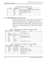
One JTAG debugging connector (J8) on the GS2200M SKB uses a 10-pin connector.
gives the pin assignments.
B.1.2 GS2200M SPI Connector Pinouts
The SPI peripheral connector (J5) is a Pmod™ Type 2A-compatible interface. It supports
attaching a SPI slave or master device. The SPI role of the GS2200M is configured via
jumper settings on header J20.
gives the pin assignments.
Table 13 JTAG Cortex Debug Connector Pin Assignments - SKB
Pin No.
Signal Name
Description
1
VDDIO
Digital IO Supply Voltage
2
JTAG_TMS
Joint Test Action Group TAP (Test Access Point) State
Control
3
GND
Ground
4
JTAG_TCK
Joint Test Action Group TAP (Test Access Point) Clocking
5
GND
Ground
6
JTAG_TDO
Joint Test Action Group TAP (Test Access Point) Data Output
7
NC
Not Connected
8
JTAG_TDI
Joint Test Action Group TAP (Test Access Point) Data Input
9
NC
Not Connected
10
EXT_RESET_n
External reset


