NOTE:
•
carefully follow these instructions when installing.
•
do not overtighten screws.
•
use of power driver is not recommended.
•
fully remove the Trilock prior to painting the door
to avoid harming the product's finish.
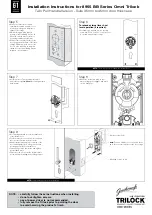
Step 13
Fixing of double pull handle
Note:
Suitable for solid doors only
• Check and make sure that the inside & outside faceplates ar
e lined up
straight and square with the door
.
• Once the desired position of the inside & outside faceplate has been
confirmed, mark the centre of the hole at the top of the faceplate and
proceed to drill a suitable hole.
Note:
When drilling the hole drill hole
from both sides of the door with a 9mm drill bit.
• On the inside faceplate, hold the optional r
ectangular plastic washer
centred over the hole against the door surface.
• Then hold the unthr
eaded bush onto the outside faceplate, ensuring
the larger section of the bush, as marked ‘A’ in illustration, is facing
the door.
• Then, fr
om the same side, install the suitable M8 screw through the
bush and optional plastic washer (if used) and through the door.
• Then, fr
om the outside faceplate fit the threaded bush
• Tighten M8 scr
ew securely with suitable screwdriver.
• Place the pull handle over top of 2 mounting bushes.
• Line up the pull handle so that it is lined up straight and squar
e.
Insert the grub screws and tighten with allen key provided
Step 10
• For single cylinder applications install inter
nal
turnbutton now by tightening grub-screw onto
protruding shaft.
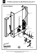
allen key
grub-screw
M8 x 82mm bolt
un-threaded
bush
rosette
timber
door
grub screw
grub screw
single
pull handle
threaded
bush
A
A
pull handle
support
25mm dia
.
plastic washer
Note: Ensure larger section of
threaded bush, as marked ‘A’ above,
is facing door
single
pull handle
door
frame
reinforced
strike plate
• Mark and drill a 25mm (1") hole to a depth of 25mm
(1"), at a corresponding height to the bolt.
• Mark and chisel recesses for strike plate and optional
reinforced strike plate.
• Screw into position using 4 wood screws as supplied.
Note:
2 larger screws should be used on reinforced
strike plate as illustrated.
Door Adjustment
1 When door is closed using finger pressure, ensure
bolt is latching into strike plate.
2 If door is rattling when in latched position. Open door,
remove strike plate & adjust anti-rattle tab & refit strike
plate to door frame. Repeat check 1.
Step 11
All door seals must be fitted prior to fitting
strike plate.
• Position the door so that the centrepoint of the
strike plate can be marked on door frame.
anti-rattle tab
Installation Instructions for 8955 BB Series Omni Trilock
T
win Pull Handle Version - Suits 35mm to 45mm door thickness


