


Page
3 of 14
GAI-Tronics 6-Channel Radio
Pub.: 42004-325A
f:\standard ioms - current release\42004 instr. manuals\42004-325a.doc
10/00
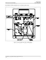
Power Connector
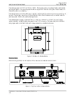
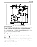
Refer to the Figure 3 for the locations of the connectors. The pinout for the power connector is as
follows:
Pin No. Function
A
Spare
B
Line hot (positive)
C
Line neutral (negative)
Speaker Connector
The speaker connector pinout is as follows:
Pin No. Function
A
Common
B
8-ohm speaker
C
16-ohm speaker
Microphone Connector
The microphone pinout is as follows:
Pin No. Function
A
Mic high
B
PTT (Transmit key)
C
Mic Lo
D
15 V dc power
Antenna Connector
The antenna connector is a coax cable connector.
Channel Selector Switch
The channel selector switch on the top of the unit provides the capability to easily select among the six
labeled channels. In addition, a lighted LED provides indication of the state of the radio.
Radio Transceiver Module
The radio transceiver module is 450 MHz and the six channel frequencies may be factory-programmed to
the customer’s specifications. The frequencies can be programmed in steps of 12.5 kHz. The radio
transceiver can also be programmed for CTCSS.
Note:
When the radio transceiver module is programmed for CTCSS or DPL it can only communicate
with other radios that have the same CTCSS or DPL programming.