Page
13 of 14
GAI-Tronics 6-Channel Radio
Pub.: 42004-325A
f:\standard ioms - current release\42004 instr. manuals\42004-325a.doc
10/00
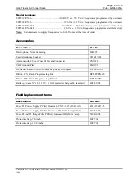
Fuse Replacement
CAUTION
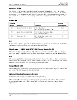
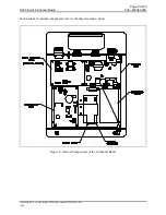
For continued safe operation, replace fuses with the same type (See Field Replacement Items):
•
Power supply PCBA fuse F1 is a Bussman C515S 1.25A SB 2AG
•
Power supply PCBA fuse F2 is a Bussman Slo-Blo GMA 5A 250 V
•
Surge filter PCBA fuses F4 and F5 is a Bussman Slo-Blo GMA 2A
Battery Replacement
The optional standby/emergency battery is designed to have a shelf life of approximately two years, but
battery life may be reduced depending on use. The battery is automatically re-charged during normal
radio usage. If the battery fails to operate the radio during a brief power interruption, the battery may
need to be replaced.
Replace the battery (Part No. 40201-004) as follows:
1.
Disconnect the cable connectors at the top of the battery, by sliding them off.
2.
Remove the two screws on the left of the battery mounting bracket.
3.
Slide the bracket to the left and lift it out of the key hole slot.
4.
Reverse the process to install the new battery.
Performance Specifications
Color ................................................................................................................................................ Black
Construction ................................................................................................. Dust-resistant steel enclosure
Physical Size ................................................................................... 14.125 H x 11.250 W x 3.00 D inches
Weight.............................................................................................................................................10 lbs.
Temperature Range............................................................................................................ -30ºC to +60ºC
Humidity ...................................................................................................................90% non-condensing
270 V dc option
Supply Voltage Range ............................................................. 200 to 350 V dc range, (270 V dc nominal)
Power Consumed......................................................................................... 8 W Standby/30 W maximum
Supply Voltage Filtering.................................................................................. Two stage LC, RES, MOV
110/220 V ac option
Supply Voltage Range ........................................ 85 to 260 V ac range, (50/60 Hz; 110/220 V ac nominal)
Power Consumed......................................................................................... 8 W Standby/30 W maximum
Channel Frequencies 1 through 6 ........................................................................ As specified by customer
Speaker Amplifier......................................................................................8 watt maximum into 8/16 ohm
450 MHz Radio Transceiver ................................................................See Ritron Publication DTX-MRM
Microphone .......................................................................... MI2895 dynamic, amplified, noise canceling
Speaker..............................................................651301/102 Cast aluminum, 16-ohm with volume control
Antennas ..................................................................................................CN3614 1/4 wave whip antenna
Connections............................................................................................................. MS Series connectors
Standby/Emergency Battery Option .............................................15 minutes under maximum power drain
longer with average current drain

