background image

Pub. 42004-441H 

GAI-TRONICS  3030 KUTZTOWN RD.  READING, PA  19605 USA


610-777-1374  

  800-492-1212


  Fax:  610-796-5954 

V

ISIT WWW

.

GAI

-

TRONICS

.

COM FOR PRODUCT LITERATURE AND MANUALS


GAI


-


TR


ON


ICS


® 

A  H


U


B


B


E


L


L  C


O


M


P


A


N


Hands-free VoIP Telephone Manual 

T

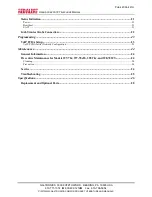
A B L E   O F

C

O N T E N T S

Confidentiality Notice .....................................................................................................................1


Product Overview ............................................................................................................................1


System Requirements and Limitations .......................................................................................... 2


Tips for VoIP Subscribers ............................................................................................................. 3


Features and Functions ................................................................................................................. 3


Operation .........................................................................................................................................3


Placing an Auto-dial Emergency Call............................................................................................ 3


Placing an Auto-dial Non-Emergency Call .................................................................................... 4


Placing a General Telephone Call ................................................................................................. 4


Receiving a Call ............................................................................................................................ 4


Multicast Broadcast ...................................................................................................................... 4


Monitoring and Reporting ............................................................................................................ 5


Installation ......................................................................................................................................5


General Information ..................................................................................................................... 5


Safety Guidelines .......................................................................................................................... 6


Station Placement ......................................................................................................................... 6


Security Hardware ........................................................................................................................ 6


Conduit Installation Details (Surface -Mount Models) ................................................................... 7


Models 393-700, 393AL-700, and 394AL-702 (Surface Mount Applications)................................. 8


Models 397-70

x

 and 398-70

x

 (Stanchion/Flush-Mount Applications) .......................................... 10


Models 397-70

x

FS and 398-701FS (Flush-Mount Applications) .................................................. 15


Setup ..............................................................................................................................................18


Field Wiring ................................................................................................................................ 18


Power...................................................................................................................................................................................... 18
Network ................................................................................................................................................................................. 18
I/O ........................................................................................................................................................................................... 20
Reco mmended Cab ling  ....................................................................................................................................................... 20

VoIP Telephone Input Contacts .................................................................................................. 21


VoIP Telephone Output Contacts ............................................................................................... 21


Summary of Contents for RED ALERT

Page 1: ...Emergency Call 3 Placing an Auto dial Non Emergency Call 4 Placing a General Telephone Call 4 Receiving a Call 4 Multicast Broadcast 4 Monitoring and Reporting 5 Installation 5 General Information 5 S...

Page 2: ...MANUALS Status Indication 21 Power 21 Heartbeat 21 EACT 21 GAI Tronics Strobe Connection 22 Programming 23 VoIP PCBA Setup 23 VoIP PCBA Initial Network Configuration 23 Maintenance 24 General Informa...

Page 3: ...any form in whole or in part directly or indirectly to any third party Product Overview RED ALERT Hands free VoIP Telephones are designed for connection to a 10 100 Mb Ethernet network These telephon...

Page 4: ...ASSISTANCE auto dial push button and CALL RECEIVED WHEN LIT LED This telephone is functionally identical to Model 397 701 397 702 Flush Mount Emergency Telephone weatherproof brushed stainless steel...

Page 5: ...nderstanding of any limitations of your 911 service Inform children babysitters and visitors about your VoIP service and its 911 limitations if any If your power is out or your internet connection is...

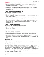
Page 6: ...98 701FS and 398 702 To place a general telephone call 1 Press the CALL push button 2 Wait for the dial tone 3 Use the keypad to dial the desired number 4 The CALL RECEIVED WHEN LIT LED will light ste...

Page 7: ...se indicated on the approval listing in the Specifications section of this manual Such installation may cause a safety hazard and consequent injury or property damage Install equipment without modific...

Page 8: ...e note proper grounding does not eliminate the need for lightning protection for the telephone or the telephone system A category 5 data line lightning surge protector is recommended for telephones su...

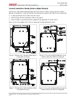
Page 9: ...hould enter the enclosure from the bottom Sealed fittings should be installed at all cable entry points Silicone sealant or equivalent should be applied around and inside all conduit entries Please re...

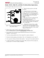
Page 10: ...or Model 393 700 only Create a conduit access hole using a Greenlee type punch that is equivalent in size to the conduit diameter Bottom entry is strongly recommended Insert a conduit fitting in the a...

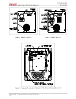
Page 11: ...IP TELEPHONE MANUAL PAGE 9 OF 28 P Standard IOMs Current Release 42004 Instr Manuals 42004 441H docx 07 16 Figure 6 Model 393AL 700 Figure 7 Model 394AL 702 Figure 8 Component Locations for Models 393...

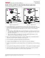
Page 12: ...anel assembly mounts directly to the enclosure back box is not required When mounting outdoors the installation of a customer supplied surge suppressor on the Ethernet line is recommended and the powe...

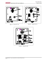
Page 13: ...2004 441H HANDS FREE VOIP TELEPHONE MANUAL PAGE 11 OF 28 P Standard IOMs Current Release 42004 Instr Manuals 42004 441H docx 07 16 Figure 11 Model 397 702 R Figure 12 Model 398 701 Figure 13 Model 398...

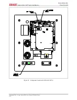
Page 14: ...PUB 42004 441H HANDS FREE VOIP TELEPHONE MANUAL PAGE 12 OF 28 P Standard IOMs Current Release 42004 Instr Manuals 42004 441H docx 07 16 Figure 14 Component Locations for Model 398 70x...

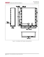
Page 15: ...PUB 42004 441H HANDS FREE VOIP TELEPHONE MANUAL PAGE 13 OF 28 P Standard IOMs Current Release 42004 Instr Manuals 42004 441H docx 07 16 Figure 15 Flush Mount VoIP Telephone Mounting Details...

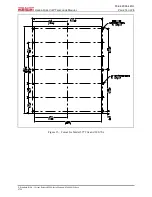
Page 16: ...PUB 42004 441H HANDS FREE VOIP TELEPHONE MANUAL PAGE 14 OF 28 P Standard IOMs Current Release 42004 Instr Manuals 42004 441H docx 07 16 Figure 16 Cutout for Model 397 70x and 398 70x...

Page 17: ...suppressor customer supplied should also be installed if local power is used 2 Remove the tapered plug s as necessary from cable entry holes and feed all cabling into the back box See the Field Wiring...

Page 18: ...41H HANDS FREE VOIP TELEPHONE MANUAL PAGE 16 OF 28 P Standard IOMs Current Release 42004 Instr Manuals 42004 441H docx 07 16 R Figure 19 Model 398 701FS Figure 20 Model 397 700FS 397 701FS and 398 701...

Page 19: ...PUB 42004 441H HANDS FREE VOIP TELEPHONE MANUAL PAGE 17 OF 28 P Standard IOMs Current Release 42004 Instr Manuals 42004 441H docx 07 16 Figure 21 Cutout for Model 397 700FS 397 701FS and 398 701FS...

Page 20: ...as indicated in your PoE equipment manual Local Power When PoE is not available a separate isolated 24 to 48 V dc power supply is required See the Replacement and Optional Parts chart on page 28 for t...

Page 21: ...PUB 42004 441H HANDS FREE VOIP TELEPHONE MANUAL PAGE 19 OF 28 P Standard IOMs Current Release 42004 Instr Manuals 42004 441H docx 07 16 Figure 22 VoIP Telephone PCB Assembly...

Page 22: ...M Common 5 IN2 Input 2 6 COM Common 7 IN1 Input 1 8 COM Common Outputs Two outputs have been provided for customer use Terminations for these outputs are provided on connector P10 See Figure 22 for th...

Page 23: ...cifications section of this manual for the output ratings Both outputs are single pole single throw contacts The function of each output is configurable Outputs can be configured for one of the follow...

Page 24: ...ment such as beacons video cameras and alarm generators to be activated when the HELP push button is pressed The relay can remain energized for the duration of the emergency call In most applications...

Page 25: ...log on via a web browser The unit is initially set with a static IP address IP address 192 168 1 2 A user name and password will be requested The initial factory settings are User Name user Password p...

Page 26: ...ess steel Wipe dry If corrosion or rusting is noticed remove with a non abrasive commercial cleanser and water Rub stained areas in the same direction as the existing grain Stubborn stains may be remo...

Page 27: ...guration Front panel push buttons are not operational Verify the push buttons are properly configured Inputs not operational Check the input connections Verify the inputs are properly configured Outpu...

Page 28: ...tity 4 Internal pull up 3 3 V dc tolerant Outputs Output 1 8 A 30 V ac dc resistive load Output 2 8 A 30 V ac dc resistive load Indicators External Off hook indicator light Internal on VoIP PCBA Power...

Page 29: ...in 257 3 193 8 mm Weight Model 397 700 6 5 lb 2 9 kg Model 397 701 6 5 lb 2 9 kg Model 397 702 7 0 lb 3 2 kg Model 398 701 7 2 lb 3 3 kg Model 398 702 7 2 lb 3 3 kg Models 397 700FS 397 701FS and 398...

Page 30: ...CBA Keypad metallic 51035 019 PCBA Keypad Assembly with Connector 12542 002 Security Screws Torx T 25 inch Pack of 15 12516 003 Security Screws Torx T 25 1 1 8 inches Pack of 10 12520 009 Push Button...

Page 31: ...of the Contractor s personnel from the work site Re performance of services shall be Buyer s sole and exclusive remedy and in no event shall GAI Tronics warranty obligations with respect to services e...

Reviews: