background image

Pub. 42004-455B 

Model 352-101, 352-102, 352-103, & 352-104 Div. 1 SMART Hazardous Area Telephones  Page 9 of 17 

f:\standard ioms - current release\42004 instr. manuals\42004-455b.doc 
02/13 

3.


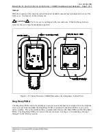
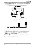
When a Ring Relay PCBA option is present, connect incoming 120 V ac power to the TB1 terminal 
block.  See Figure 8. 


Figure 8.  Ring Relay PCBA 


Figure 9. 

4.


Connect the external sounder or beacon to TB2, for activation with an incoming telephone call. 

5.


Reconnect the communication cable between the Main PCBA and Ring Relay PCBA, if 
disconnected, before reattaching the front cover. 

WARNING


  Any external equipment connected to the Ring Relay PCBA must be rated for the 

hazardous area where it will be located.  Improper installation or equipment may cause a safety hazard 
and consequent injury or property damage. 

Summary of Contents for 352-101

Page 1: ... form in whole or in part directly or indirectly to any third party General Information GAI Tronics Class I Division 1 SMART Hazardous Area Telephones are constructed of cast aluminum and are weatherproof and corrosion resistant They combine standard telephone operation with GAI Tronics Self Monitoring and Reporting Telephone SMART technology to provide optimum performance and flexibility When use...

Page 2: ...grammed to generate an auto dial maintenance call when certain sensor events are discovered Access to the SMART Telephone s maintenance mode is restricted through the use of the maintenance access PIN The maintenance access PIN should be distributed only to trained maintenance personnel Installation Installation Guidelines These enclosures must be installed by trained qualified and competent perso...

Page 3: ...g and coiled ground wires Please note proper grounding does not eliminate the need for lightning protection for the telephone or the telephone system NEVER install telephone during a lightning storm Install a UL Listed lightning arrestor on any telephone installed where the telephone or telephone cable is at risk of being exposed to lightning strikes The lightning arrestor must be installed as clo...

Page 4: ...Refer to Figure 2 The suggested mounting height is 48 inches to the bottom of the enclosure NOTE Refer to the Killark Installation Operation and Maintenance Data Sheet enclosed with the unit for additional enclosure information Figure 2 352 Series Division 1 SMART Hazardous Area Telephone Enclosure Mounting Details Cable Entries Refer to Figure 3 for the NPT conduit entries Ensure any unused openi...

Page 5: ...02 each contain a handset with an approved gland standard keypad volume control button and applicable approval labeling The handset rests on a cradle which has a magnetic reed switch located behind it to signal an off hook condition The enclosure is sealed with ten cover mounting bolts located around the perimeter of the enclosure s flange See Figure 4 Figure 4 352 Series Division 1 SMART Hazardou...

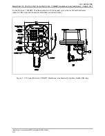
Page 6: ...ndard ioms current release 42004 instr manuals 42004 455b doc 02 13 For the Division 1 SMART Telephone models with the headset option the cradle and handset are replaced with a removable headset and headset activation bracket Figure 5 352 Series Division 1 SMART Hazardous Area Headset Telephone Outline Drawing ...

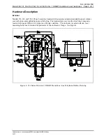
Page 7: ...sure When the flange bolts are removed the cover must be adequately supported Figure 6 352 Series Division 1 SMART Hazardous Area Telephone Internal View Ring Relay PCBA The Ring Relay PCBA allows the telephone to activate an external beacon or sounder when the telephone receives a call When installed the Ring Relay PCBA is connected to the Main PCBA via a two wire cable assembly This cable assemb...

Page 8: ...er bolts are removed the cover must be adequately supported 1 While supporting the front cover remove the ten cover bolts from the enclosure flange Pull the front cover far enough away to expose the internal connections and disconnect any wiring between the front cover and rear enclosure Place the front cover aside 2 Connect the incoming subscriber line or the telephone line suppressor if applicab...

Page 9: ...e 8 Figure 8 Ring Relay PCBA Figure 9 4 Connect the external sounder or beacon to TB2 for activation with an incoming telephone call 5 Reconnect the communication cable between the Main PCBA and Ring Relay PCBA if disconnected before reattaching the front cover WARNING Any external equipment connected to the Ring Relay PCBA must be rated for the hazardous area where it will be located Improper ins...

Page 10: ...t the telephone PolarityConfiguration Factory Setting Non polarity sensitive This telephone can be configured to be polarity or non polarity sensitive With the non polarized setting the telephone operates with the telephone line s positive terminal connected to either the tip or the ring With the polarized setting the telephone only operates with the telephone line s positive terminal connected to...

Page 11: ...or control a door latch gate relay solenoid alarm etc from the called party location Extreme Cold Temperature Operation GAI Tronics 352 Series Division 1 SMART Telephones are equipped for operation in extremely cold temperatures ranging to 40º C Operation at these temperatures requires 5 V dc to be supplied to the telephone To connect the power remove the jumper from header P17 pins 3 and 4 and pl...

Page 12: ...nd column of Table 1 Basic Programming Commands for the features that you need Having your programming information written down allows you to enter the key sequence at a steady pace Complete the following steps to enter the programming sequence from a remote DTMF telephone 1 Call the SMART Telephone to be programmed Do not use a cellular telephone 2 Listen for a confirmation tone during ringing wh...

Page 13: ...32400 This number represents the number of half second increments of duration Entering 0 results in a call time out of 4 5 hours Enter 37 120 32400 to assign a time limit or change an existing time limit 37 Data transfer command 120 32400 Call duration 60 16 200 seconds 0 4 5 hours See example below End of sequence indicator Multiply the desired time limit in minutes by 120 to determine the call d...

Page 14: ...et receiver volume control which is located on the front cover keypad can be adjusted to the desired level by pressing the volume control push button NOTE Pressing the volume control push button increases the volume in 5 dB increments The volume starts at 0 dB and increases to a maximum volume of 20 dB Pressing the volume control push button a fifth time will return the volume to 0 dB 3 Dial the d...

Page 15: ...e two ends together Figure 11 2 To place a call remove the headset from the headset activation bracket and flip the headset bracket forward to its preset position See Figure 11 3 The handset receiver volume control which is located on the front cover keypad can be adjusted to the desired level by pressing the volume control push button NOTE Pressing the volume control push button increases the vol...

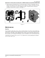
Page 16: ...disconnected reattach the sealing cap to the end of the receptacle See Figure 12 Figure 12 Maintenance Service If your telephone requires depot service contact your Regional Service Center for a return authorization number RA Equipment should be shipped prepaid to GAI Tronics with a return authorization number and a purchase order number If the equipment is under warranty repairs will be made with...

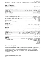
Page 17: ...h standard Connections Internal screw type barrier terminal blocks Dimensions Outside 10 25 W 12 25 H 9 50 D inches 260 3 311 1 241 3 mm Mounting Wall or column four 3 8 inch 10 mm mounting feet with slots Shipping weight 30 0 lbs 13 6 kg Net weight 28 0 lbs 12 7 kg Approvals NRTL listed Hazardous locations Class I Division 1 Groups B C D USA and Canada Class II Division 1 Groups F G Class III Div...

Page 18: ... of the Contractor s personnel from the work site Re performance of services shall be Buyer s sole and exclusive remedy and in no event shall GAI Tronics warranty obligations with respect to services exceed 100 of the total cost of the services provided hereunder Warranty Periods Every claim by Buyer alleging a defect in the goods and or services provided hereunder shall be deemed waived unless su...

Reviews: