Pub. 42003-149
M
ODEL
12550-102 R
ECEIVER
A
MPLIFIER
R
EPLACEMENT
K
IT
Page:
2 of 3
f:\standard ioms - current release\kits (42003)\42003-149.doc
8/95
3.
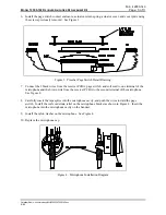
Remove the 2 screws that secure the handset page switch to the handset. Carefully remove the page
switch cover plate, actuator cover, return spring, actuator, and contact enclosure from the handset
handle. See Figure 3.
4.
Unscrew the receiver cap, and carefully remove the receiver/amplifier assembly.
5.
Discard the old receiver and amplifier assembly.
Installing the New Receiver and Amplifier PCBA
1.
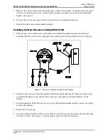
Place the new receiver element on a flat surface, and install the amplifier printed circuit board
assembly (PCBA) on the receiver using the brass eyelets and screws provided as shown in Figure 2.
2.
Carefully insert the wires from the amplifier PCBA into the handset handle (black and brown wires
go to the microphone cavity, and the white wire goes to the page switch cutout midway on the
handle).
3.
Insert the amplifier PCBA into the receiver cavity of the handset handle until the receiver is properly
seated in the handset.
4.
Replace the receiver cap.
5.
Insert the spade terminal from the receiver white wire into the jumper clip, along with the white wire
from the coil cord. See Figure 1. Tape the jumper clip with vinyl electrical tape.
Figure 2. Receiver/Amplifier Installation Diagram


