background image

7

/

10 pages

102-1235 V-0.25/12.5-120L

2.2

Φ65*1,Φ51*1

250

12.5

80 240/50

120

102-1236 V-0.25/12.5-180L

2.2

Φ65*1,Φ51*1

250

12.5

80 240/50

180

102-1237 V-0.25/12.5-230L

2.2

Φ65*1,Φ51*1

250

12.5

80 240/50

230

102-1238 W-0.36/12.5-120L

3

Φ65*2,Φ51*1

360

12.5

90 415/50

120

102-1239 W-0.36/12.5-180L

3

Φ65*2,Φ51*1

360

12.5

90 415/50

180

102-1240 W-0.36/12.5-230L

3

Φ65*2,Φ51*1

360

12.5

90 415/50

230

102-1241 W-0.36/12.5-300L

3

Φ65*2,Φ51*1

360

12.5

90 415/50

300

102-1242 V-0.6/12.5-180L

4

Φ90*1,Φ65*1

600

12.5

≤100 415/50

180

102-1243 V-0.6/12.5-230L

4

Φ90*1,Φ65*1

600

12.5

≤100 415/50

230

102-1244 V-0.6/12.5-300L

4

Φ90*1,Φ65*1

600

12.5

≤100 415/50

300

102-1245 V-0.6/12.5-400L

4

Φ90*1,Φ65*1

600

12.5

≤100 415/50

400

102-1246 W-0.8/12.5-230L

5.5

Φ80*2,Φ65*1

800

12.5

110 415/50

230

102-1247 W-0.8/12.5-300L

5.5

Φ80*2,Φ65*1

800

12.5

110 415/50

300

102-1248 W-0.8/12.5-400L

5.5

Φ80*2,Φ65*1

800

12.5

110 415/50

400

102-1249 W-0.8/12.5-500L

5.5

Φ80*2,Φ65*1

800

12.5

110 415/50

500

102-1250 W-0.9/12.5-300L

7.5

Φ90*2,Φ65*1

900

12.5

110 415/50

300

102-1251 W-0.9/12.5-400L

7.5

Φ90*2,Φ65*1

900

12.5

110 415/50

400

102-1252 W-0.9/12.5-500L

7.5

Φ90*2,Φ65*1

900

12.5

110 415/50

500

102-1253 4V-1.05/12.5-300L 7.5

Φ105*2,Φ55*2

1050

12.5

120 415/50

300

102-1254 4V-1.05/12.5-400L 7.5

Φ105*2,Φ55*2

1050

12.5

120 415/50

400

102-1255 4V-1.05/12.5-500L 7.5

Φ105*2,Φ55*2

1050

12.5

120 415/50

500

Summary of Contents for 102-1201

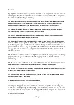
Page 1: ...1 10 pages BELT DRIVEN AIR COMPRESSORS PRODUCT MANUAL BEFORE OPERATION SHOULD BE FAMILIAR WITH THE PRODUCT MANUAL FIRST ...

Page 2: ...ler the lubricating oil shall reach the halfway mark in the Oil Indicator Glass 2 Check the motor rotation direction as indicated by the label in fence cover in case motor is running at wrong direction the air compressor shall be stopped immediately for three phase air compressor you need to exchange two phase wires to make motor run at correct direction 3 Hand is strictly prohibited to be placed ...

Page 3: ...ssor away from spraying area as far as possible 2 DISCONNECT POWER SUPPLY AND RELEASE ALL PRESSURE FROM THE SYSTEM BEFORE ATTEMPTING TO INSTALL SERVICE RELOCATE OR PERFORM ANY MAINTENANCE OF THE AIR COMPRESSOR 3 Electric motor and D O L Starter must be securely and adequately connected with earthing wires to prevent of electric shock risks 4 Do not weld on the air tank of this air compressor Weldi...

Page 4: ...iver tank pressure test shall be done every two year The surface of the receiver tank should be checked every year if there are serious rust bumps or pressure test failure then the air receiver tank should be disposed 14 Pull the safety valve at least on a weekly basis to check whether safety valve is functioning properly if the safety valve is found not functioning properly then it shall be repla...

Page 5: ...ity Liter KW MM LPM Bar 102 1201 V 0 12 8 50L 1 1 Φ51 2 120 8 70 240 50 50 102 1202 V 0 12 8 70L 1 1 Φ51 2 120 8 70 240 50 70 102 1203 V 0 12 8 90L 1 1 Φ51 2 120 8 70 240 50 90 102 1204 V 0 17 8 70L 1 5 Φ51 2 170 8 70 240 50 70 102 1205 V 0 17 8 90L 1 5 Φ51 2 170 8 70 240 50 90 102 1206 V 0 17 8 120L 1 5 Φ51 2 170 8 70 240 50 120 102 1258 V 0 17 8 150L 1 5 Φ51 2 170 8 70 240 50 150 102 1207 V 0 17...

Page 6: ...0 415 50 300 102 1223 W 0 9 8 500L 7 5 Φ90 3 900 8 110 415 50 400 102 1224 W 1 0 8 300L 7 5 Φ90 3 1000 8 110 415 50 500 102 1225 W 1 0 8 400L 7 5 Φ90 3 1000 8 110 415 50 300 102 1226 W 1 0 8 500L 7 5 Φ90 3 1000 8 110 415 50 400 102 1227 W 1 25 8 300L 7 5 Φ95 3 1250 8 120 415 50 300 102 1228 W 1 25 8 400L 7 5 Φ95 3 1250 8 120 415 50 400 102 1229 W 1 25 8 500L 7 5 Φ95 3 1250 8 120 415 50 500 102 123...

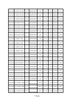
Page 7: ...02 1244 V 0 6 12 5 300L 4 Φ90 1 Φ65 1 600 12 5 100 415 50 300 102 1245 V 0 6 12 5 400L 4 Φ90 1 Φ65 1 600 12 5 100 415 50 400 102 1246 W 0 8 12 5 230L 5 5 Φ80 2 Φ65 1 800 12 5 110 415 50 230 102 1247 W 0 8 12 5 300L 5 5 Φ80 2 Φ65 1 800 12 5 110 415 50 300 102 1248 W 0 8 12 5 400L 5 5 Φ80 2 Φ65 1 800 12 5 110 415 50 400 102 1249 W 0 8 12 5 500L 5 5 Φ80 2 Φ65 1 800 12 5 110 415 50 500 102 1250 W 0 9 ...

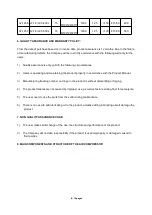
Page 8: ...oduct properly in accordance with the Product Manual 3 Manufacturing tracking number and logo in the product is without dismantling or forging 4 The product failures are not caused by improper use as well as factors arising from force majeure 5 The user need to use the parts from the seller during maintenance 6 There is no need to add lubricating oil to the product actually adding lubricating oil ...

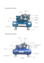
Page 9: ...Motor Air receiver tank Pressure switch Wheel One way check valve Silencer Oil filling plug Pressure meter Handle Oil filling plug Pump head Pressure switch and meter Safety valve Ball valve Ball valve Safety valve One way check valve Silencer Motor D O L Starter Air receiver tank Wheel ...

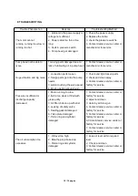
Page 10: ...y worn 1 Check and tight loosen parts 2 check and clean away 3 Contact dealer service center or factory for service Pressure insufficient or discharge capacity decreased 1 Motor running too low 2 belt is too slack or filled with grease dirty 3 Air filter choken up with dust 4 Leaking of safety valve 5 Sealing gasket damaged 6 Valve plate damaged 7 Piston ring and cylinder damaged 1 Contact dealer ...

Reviews: