GAGEMAKER MRP-1500 Operation Manual Download Page 56

Pitch Diameter Gage Operation Manual


Models MRP 1500/2500/3500


Copyright © 2018 Gagemaker. All rights reserved


56 

MRP Accuracy Measurement Factors 

 
Thread Addendum Measurements


Accurate MRP measurements are based on positioning the pivot shoe on the crest cone of the 

thread at a prescribed distance from the face of the connector. If the distance from the pitch line 

to the crest cone is accurate, then readings taken from at the crest cone directly reflect the 

accuracy of the pitch diameter. 


Problems occur when the threading process pushes a thread flank back, to decrease standoff of 

a ring or plug. When the flanks are relocated, the distance from the pitch line to the crest is 

changed. 

Thread Addendum

 is the change in the distance from the pitch line to the crest cone. 

Changes in thread addendum affect the relationship of measurements taken with the MRP gage 

and measurements taken with ring and plug gages. 


The diagrams below describe how plus and minus addendum is detected and how to compensate 

for its effect on the readings of the MRP gage. 


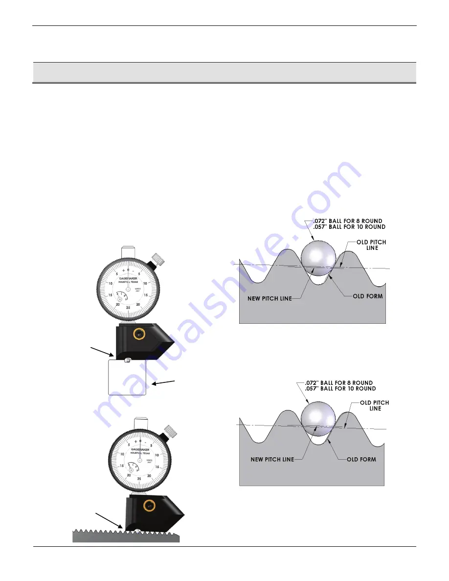
Plus Addendum – Wide Groove – Large Reading 

Mating part will have less standoff 

P.D. Correction for Plus Addendum: 

Pin = Subtract 2 times deviation from P.D. 

Box = Add 2 times deviation to P.D. 

Minus Addendum – Narrow Groove – Small Reading 

Mating part will have more standoff 

P.D. Correction for Minus Addendum: 

Pin = Add 2 times deviation to P.D. 

Box = Subtract 2 times deviation from P.D. 

Setting Standard 

Seat the contact point into 
the standard’s groove 


Rest the gage on  
the thread crests 


Zero the indicator while the gage (TA-3002) is 

on the standard (TAS-1014) 

TAS-1014 

Summary of Contents for MRP-1500

Page 1: ...MRP Pitch Diameter Gage Models 1500 2500 3500 OPERATION MANUAL...

Page 2: ...ter Gage Operation Manual Models MRP 1500 2500 3500 Copyright 2018 Gagemaker All rights reserved 2 2018 Gagemaker LP MRP and Gagemaker are registered trademarks of Gagemaker LP All rights reserved OMM...

Page 3: ...nal Parts 28 Setup Procedures for Internal Measurements MRP Dimensional Limits Chart 31 Setting Up the MRP Gage for Internal Measurements 32 Zeroing the MRP Gage for Internal Measurements Using Rod St...

Page 4: ...ng Dimensions for the MRP Gage API Line Pipe Connections 1 to 20 62 API NUE Connections to 4 62 API EUE Connections to 4 63 API STC Connections 4 to 20 63 API LTC Connections 4 to 20 64 API Buttress C...

Page 5: ...diameters from 1 to 4 the MRP 2500 fits diameters in the 5 to 13 3 8 range and the MRP 3500 tackles the 8 5 8 to 20 diameter range The solid frame construction allows the MRP gage to set securely on...

Page 6: ...y MRP 1500 1 5 MRP 2510 4 9 5 8 MRP 2520 4 13 3 8 MRP 3500 8 5 8 20 1 8 2500 3500 Internal External Lower Arm Standard 7 Reach 10 Reach 1 2 Upper Block 1 9 1500 Internal External Upper Arm 1 3 Upper W...

Page 7: ...Models MRP 1500 2500 3500 Copyright 2018 Gagemaker All rights reserved 7 B MIN B MAX C MAX C MIN A MAX A MIN C MIN B MAX B MIN C MAX A MIN A MAX MRP External Setup Dimensional Limits MRP Internal Set...

Page 8: ...t below Locate the measurement you need on the chart and determine if the MRP gage model falls within the measurement range MRP Gage Model Application A Measurement MIN MAX Diameter at Pivot Shoe with...

Page 9: ...pper and lower block correctly and installing the arms and pivot shoes on the gage 1 Before beginning ensure the upper and lower blocks are positioned properly by inserting the arms as shown in the di...

Page 10: ...Tighten the set screws to secure the upper block 6 Using a 3 16 hex wrench loosen the set screws in the lower block and remove the lower wear pad 7 Rotate the lower block and wear pad 180 degrees and...

Page 11: ...n The arms align with the ball on the inside of each block 10 Insert the indicator into the upper arm Note You ll need to remove the contact point from the indicator stem before inserting the indicato...

Page 12: ...MRP Gage for External Measurements continued 14 Align each pivot shoe parallel with the groove on each arm 15 Gently tighten the binder nut with pliers to secure Be careful not to over tighten the bi...

Page 13: ...e readings the MRP gage should be zeroed on a standard once during each shift at a minimum 1 Locate the appropriate MRP rod setting standard for the desired connector or dimension Note MRP rod standar...

Page 14: ...the end of the pivot shoe contacts the B standard 4 Tighten the two set screws on the lower block to secure the arm Repeat with the upper arm 5 Remove the standard 6 Using the 3 16 hex wrench loosen t...

Page 15: ...8 Gagemaker All rights reserved 15 Zeroing the MRP Gage for External Measurements Using Rod Standards 9 Using the 3 16 hex wrench tighten the set screws on the lower block 10 Turn the indicator dial o...

Page 16: ...etting Note Note the position of the small revolution counter on the indicator before removing the gage Place a piece of masking tape on the backside of the indicator and record the dial setting of th...

Page 17: ...e standard 1 8 hex wrench supplied with gage To ensure consistent and accurate readings the MRP gage should be zeroed on a standard once during each shift at a minimum 1 Locate the appropriate frame s...

Page 18: ...ments Using Frame Standards 4 Using the 1 8 hex wrench loosen the two set screws on the upper block until the arm slides up and down freely Repeat with the lower block 5 Position both pivot shoes in t...

Page 19: ...ward the lower block approximately 050 Then slide the lower block until it contacts the frame setting standard to give the MRP the proper preload 8 Once positioned with the proper preload tighten the...

Page 20: ...Note Note the position of the small revolution counter on the indicator before removing the gage Place a piece of masking tape on the backside of the indicator and record the dial setting of the small...

Page 21: ...nce during each shift at a minimum 1 Turn on the MIC TRAC CPU 2 Clean both of the receiver pads and the mounting surfaces of the taper blocks using a cloth 3 Place the taper block against the receiver...

Page 22: ...s reserved 22 Zeroing the MRP Gage for External Measurements Using the MIC TRAC 7 Turn the coarse adjust knob counterclockwise to bring the taper blocks together 8 Press the Reference Pulse pad on the...

Page 23: ...ons for the MRP Gage tables 11 Locate the table for the type of connection being measured 12 Determine the pipe size and use the dimension in the Pin Dimensions External CPU Reading column 13 Turn the...

Page 24: ...the upper block 20 Locate the proper gage setting dimensions at the back of this manual refer to in the MIC TRAC Setting Dimensions for the MRP Gage tables 21 Locate the table for the type of connect...

Page 25: ...sing the MIC TRAC 23 Using a scale adjust both arms to the proper MIC TRAC setting dimension 24 Tighten the two set screws on the upper and lower blocks to secure the arm 25 Place the MRP gage on the...

Page 26: ...ge toward the lower block approximately 050 Then slide the lower block until it contacts the right taper block to give the MRP the proper preload 28 Once positioned with the proper preload tighten the...

Page 27: ...amp Note Note the position of the small revolution counter on the indicator before removing the gage Place a piece of masking tape on the backside of the indicator and record the dial setting of the s...

Page 28: ...out of roundness of a piece of pipe or coupling The average of the largest and smallest readings taken on the MRP produces a round diameter reading However no pipe is exactly rounded So the smallest...

Page 29: ...the MRP Inspection Tolerance Guidelines at the back of this manual to determine the accuracy of the diameter 1 Rotate the gage 90 degrees and sweep for the largest reading again If your second readin...

Page 30: ...ck of this manual Example Largest Diameter Reading Smallest Diameter Reading 2 Pitch Diameter 005 002 0015 3 To calculate the ovality Subtract the smallest indicator reading from the largest indicator...

Page 31: ...rt below Locate the measurement you need on the chart and determine if the MRP gage model falls within the measurement range MRP Gage Model Application A Measurement MIN MAX Diameter at Pivot Shoe wit...

Page 32: ...pper and lower block correctly and installing the arms and pivot shoes on the gage 1 Before beginning ensure the upper and lower blocks are positioned properly by inserting the arms as shown in the di...

Page 33: ...the upper block with the holes located at the right side of the MRP frame 5 Tighten the set screws to secure the upper block 6 Using a 3 16 hex wrench loosen the set screws in the lower block and remo...

Page 34: ...that the arms snap into position The arms align with the ball on the inside of each block 10 Insert the indicator into the upper arm Note You ll need to install the contact point on the indicator stem...

Page 35: ...ed 35 Setting Up the MRP Gage for Internal Measurements continued 13 Align each pivot shoe parallel with the groove on each arm 14 Gently tighten the binder nut with pliers to secure Be careful not to...

Page 36: ...e readings the MRP gage should be zeroed on a standard once during each shift at a minimum 1 Locate the appropriate MRP rod setting standard for the desired connector or dimension Note MRP rod standar...

Page 37: ...nd of the pivot shoe contacts the B standard 4 Tighten the two set screws on the lower block to secure the arm Repeat with the upper arm 5 Remove the standard 6 Using the 3 16 hex wrench loosen the se...

Page 38: ...8 Gagemaker All rights reserved 38 Zeroing the MRP Gage for Internal Measurements Using Rod Standards 9 Using the 3 16 hex wrench tighten the set screws on the lower block 10 Turn the indicator dial o...

Page 39: ...etting Note Note the position of the small revolution counter on the indicator before removing the gage Place a piece of masking tape on the backside of the indicator and record the dial setting of th...

Page 40: ...e standard 1 8 hex wrench supplied with gage To ensure consistent and accurate readings the MRP gage should be zeroed on a standard once during each shift at a minimum 1 Locate the appropriate frame s...

Page 41: ...ments Using Frame Standards 4 Using the 1 8 hex wrench loosen the two set screws on the lower block until the arm slides up and down freely Repeat with the upper block 5 Position both pivot shoes in t...

Page 42: ...toward the upper block approximately 050 Then slide the lower block back until it contacts the frame setting standard to give the MRP the proper preload 8 Once positioned with the proper preload tight...

Page 43: ...Note Note the position of the small revolution counter on the indicator before removing the gage Place a piece of masking tape on the backside of the indicator and record the dial setting of the small...

Page 44: ...nce during each shift at a minimum 1 Turn on the MIC TRAC CPU 2 Clean both of the receiver pads and the mounting surfaces of the taper blocks using a cloth 3 Place the taper block against the receiver...

Page 45: ...5 Zeroing the MRP Gage for Internal Measurements Using the MIC TRAC 7 Turn the coarse adjust knob counterclockwise to bring the taper blocks together Need verification for name of button 8 Press the I...

Page 46: ...ons for the MRP Gage tables 11 Locate the table for the type of connection being measured 12 Determine the pipe size and use the dimension in the Box Dimensions Internal CPU Reading column 13 Turn the...

Page 47: ...the upper block 18 Locate the proper gage setting dimensions at the back of this manual refer to in the MIC TRAC Setting Dimensions for the MRP Gage tables 19 Locate the table for the type of connect...

Page 48: ...of the upper and lower blocks with a hex wrench to secure the arms 21 Place the MRP gage on the MIC TRAC so the pivot shoes are positioned on the inside of the taper blocks 22 With the pivot shoe of t...

Page 49: ...easurements Using the MIC TRAC 23 Once positioned with the proper preload tighten the set screws to secure the lower block 24 While holding the lower block securely against the right taper block sweep...

Page 50: ...ll revolution counter on the indicator before removing the gage Place a piece of masking tape on the backside of the indicator and record the dial setting of the small revolution counter to eliminate...

Page 51: ...est readings taken on the MRP produces a round diameter reading However no pipe is exactly round So the smallest reading subtracted from the largest reading produces the ovality reading 1 After zeroin...

Page 52: ...er to the MRP Inspection Tolerance Guidelines at the back of this manual to determine the accuracy of the diameter 4 Rotate the gage 90 and sweep for the largest reading again If your second reading i...

Page 53: ...ck of this manual Example Largest Diameter Reading Smallest Diameter Reading 2 Pitch Diameter 005 002 0015 2 To calculate the ovality Subtract the smallest indicator reading from the largest indicator...

Page 54: ...t diameter readings on the part and taking the average of the two readings as shown in the following formula Largest Diameter Smallest Diameter Pitch Diameter 2 Example Largest Diameter Reading Smalle...

Page 55: ...ejection Connection P D Pin Box Used in Tolerance P D Pin Box New in Tolerance Ovality Pin Box in 8 Round LTC STC NUE EUE 003 in dia 2 008 004 007 2 008 004 008 3 008 004 011 4 008 004 014 5 008 004 0...

Page 56: ...um is the change in the distance from the pitch line to the crest cone Changes in thread addendum affect the relationship of measurements taken with the MRP gage and measurements taken with ring and p...

Page 57: ...ead height To determine the relationship between diameter change and ring or plug gage standoff for each type of connector use the following formula no consideration given to ovality Standoff X Taper...

Page 58: ...D to crest 500 shoe reposition factor shoe compensation factor A E7 062 500 062 0002 B Standard Shoe Location Length to handtight plane 500 1 2 shoe length B L7 812 Note The shoe reposition factor re...

Page 59: ...compensation factor A E7 062 0002 B Standard Shoe Location Length to handtight plane 1 2 shoe length B g A 312 Note The shoe compensation factor compensates for the change in diameter of the pivot sh...

Page 60: ...oss the thread s stab flank crest radii The diagram below illustrates how the step thread compensation factor is determined and how to adjust setting standards to compensate for the shoe contact Total...

Page 61: ...alculation Variables and Factors GPr Change in setting diameter due to relocating the connection gage point to coincide with the taper block gage point PDc Connector pitch diameter at crest cone PDn N...

Page 62: ...1395 1 1 900 11 375 N A 1 3795 2 2 375 11 375 1 8573 1 8545 2 2 875 8 375 2 3351 2 3105 3 3 500 8 375 2 9562 2 9355 3 4 000 8 500 3 4531 3 4355 4 4 500 8 500 3 9500 3 9355 5 5 563 8 500 5 0063 4 9985...

Page 63: ...ensions External CPU Reading Box Dimensions Internal CPU Reading 4 9 50 All 50 3 9399 3 9774 4 Others All 1 00 3 9009 3 9774 5 11 50 All 1 00 4 4087 4 4774 5 Others All 1 00 4 3930 4 4774 5 All All 1...

Page 64: ...13 Nominal Pipe Size Buttress Only Weight Per Foot Grade Distance from MRP Wear Pad to Center of Pivot Shoe Pin Dimensions External CPU Reading Box Dimensions Internal CPU Reading 4 All All 75 3 9385...

Page 65: ...yer has given Gagemaker written notice of any such claimed defect within 15 days of receipt Any defective product must be properly packed and shipped to the Gagemaker factory in Pasadena Texas USA Thi...

Page 66: ...Pitch Diameter Gage Operation Manual Models MRP 1500 2500 3500 Copyright 2018 Gagemaker All rights reserved 66...

Page 67: ......

Page 68: ...ter Gage Operation Manual Models MRP 1500 2500 3500 Gagemaker LP P O Box 87709 Houston Texas 77287 7709 712 East Southmore Ave Pasadena Texas 77502 Phone 713 472 7360 Fax 713 472 7241 Web site www gag...

Reviews: