GAGEMAKER LG-5003 Operation Manual Download Page 10

Lead Gage Operation Manual 

Model LG-5003 


10


Copyright © 2014 Gagemaker. All rights reserved


Zeroing the Lead Gage   (continued) 


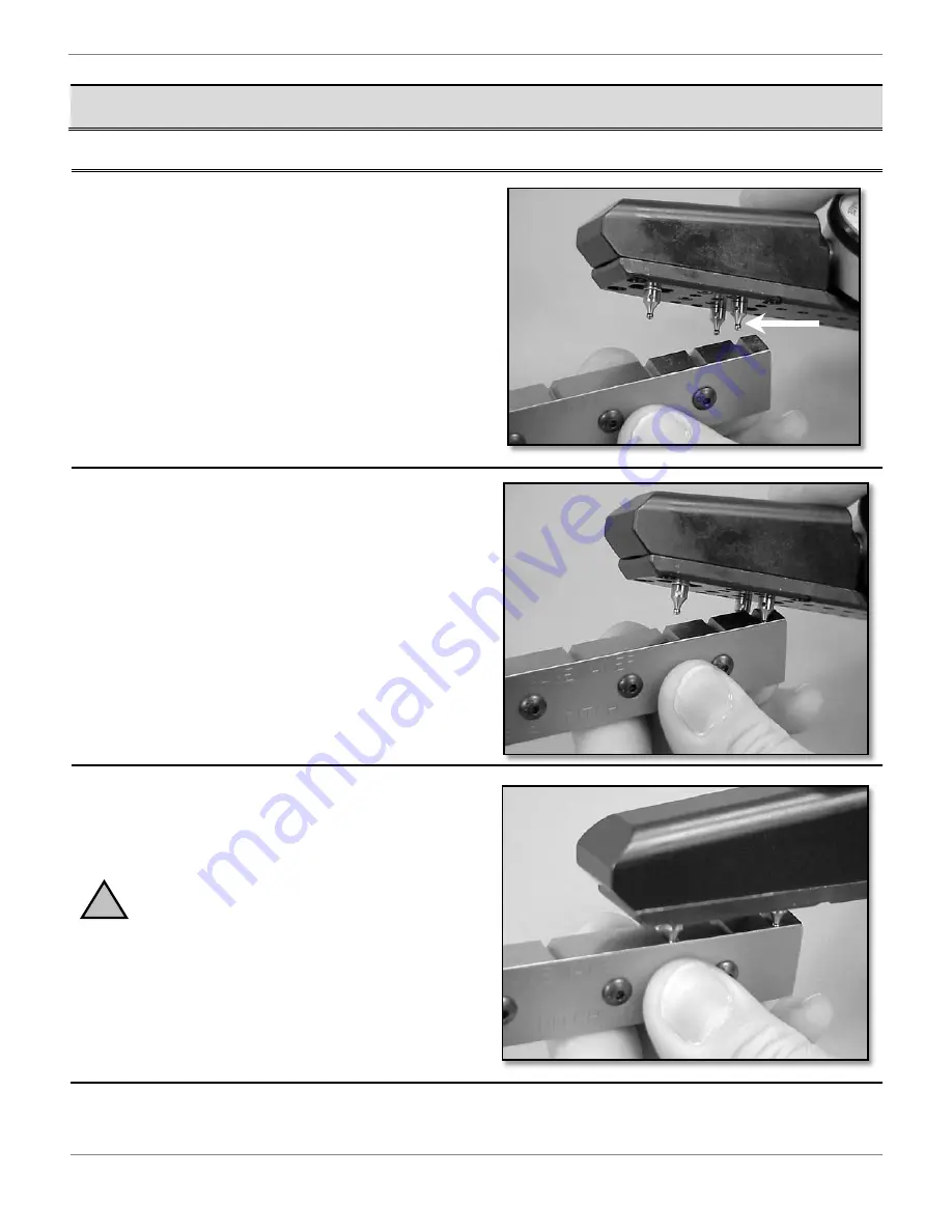
1.  Loosen the indicator clamp and place fixed 

contact point in the first groove of standard. 


2.  Slide the gage over until the fixed contact point 

seats against the fence.


3.  Place moveable contact point into the groove 

of setting. 

For Non-V threads, pull the lead gage 
toward the load flank of the groove in the 
standard. 
 
For V threads, be sure the contact points 
touch both flanks of the groove in the 
standard.


Summary of Contents for LG-5003

Page 1: ...LG 5003 Lead Gage OPERATION MANUAL ...

Page 2: ...Lead Gage Operation Manual Model LG 5003 2 Copyright 2014 Gagemaker All rights reserved 2014 Gagemaker LP ...

Page 3: ...Contents Introduction Technical Support 4 Product Information and Updates 4 Parts List 5 Setup Procedures Setting Up the Lead Gage 7 Zeroing the Lead Gage 9 Operating Procedures Inspecting Parts 12 Care and Maintenance Replacing the Indicator 14 Maintenance Tips 19 Warranty Information 19 ...

Page 4: ...hree point system to inspect thread lead Two fixed contact points at the rear of the gage and one moveable contact point at the front of the gage provide complete stability when taking thread lead measurements This unique design does not require sweeping to obtain measurements By removing the third contact point the LG 5003 is easily converted to a conventional lead gage which uses two contact poi...

Page 5: ...te LG 5003 A1 1 9 Indicator set screw LG 5003 A9 1 2 Bearing assembly LG 5003 A2 1 10 Handle LG 5003 A10 1 3 Bearing alone LG 5003 A3 1 11 Handle cap screw LG 5003 A11 2 4 Bearing cap screw LG 5003 A4 4 12 Trigger LG 5003 A12 1 5 Spring LG 5003 A5 1 13 Trigger cap screw LG 5003 A13 1 6 Nose cover LG 5003 A6 1 14 Flat contact point P 500 1 7 Nose cap screw LG 5003 A7 4 15 Contact point T072 3 8 Spl...

Page 6: ...44T 4 5 pitch T128 4 pitch T128T 5 pitch T115 5 pitch T105T 5 5 pitch T105 6 7 pitch T090T 6 pitch T096 8 pitch T062T 8 pitch T072 10 pitch T050T 10 pitch T057 12 pitch T041T 11 12 pitch T050 14 pitch T041T 14 pitch T041 16 pitch T032T 16 pitch T041 18 pitch T032 API Threads Connection Type Contact Point Diameter Thread Pitch Contact Point Model Number Hughes Slim Line H 90 0 235 3 T235 All Hughes...

Page 7: ... thread roots example shows 8 TPI The increments in the lead gage are set at intervals from 1 4 2 Select the correct contact points to install in the gage based on the connection thread type and pitch size refer to tables on previous page 3 Verify the diameter of the contact point ball using calipers or a micrometer 4 Install a contact point into the moveable holder at the front of the gage 8 4 0 ...

Page 8: ...right 2014 Gagemaker All rights reserved Setting Up the Lead Gage continued 5 Install the remaining two contact points into the proper holes at the rear of the gage 6 Once installed insert a paper clip into the hole in each contact point and tighten ...

Page 9: ... API 8 Round Casing Tubing Drill Pipe All 10 Round Tubing 8 10 LS 1001 Straight Threads 6 18 Pitch 4 Length8 10 V Form Tubing straight 0 8 10 LS 1002 11 V API Line Pipe 11 LS 1003 Straight Threads Line Pipe 0 11 LS 1004 API Buttress Casing Internal External 14 13 5 LS 1005 API Buttress Casing Internal External 16 Larger 1 5 LS 1006 6 API Reg 4 5 6 API Full Hole 2 3 5 Hughes Xtra Hole 2 2 4 Hughes ...

Page 10: ...ixed contact point in the first groove of standard 2 Slide the gage over until the fixed contact point seats against the fence 3 Place moveable contact point into the groove of setting For Non V threads pull the lead gage toward the load flank of the groove in the standard For V threads be sure the contact points touch both flanks of the groove in the standard ...

Page 11: ... Copyright 2014 Gagemaker All rights reserved 11 Zeroing the Lead Gage continued 4 With the two contact points properly seated in the grooves of the standard turn the indicator dial to align the needle with zero 5 Tighten the indicator clamp ...

Page 12: ...ng the lead gage involves placing the lead gage s contact points in the flanks of the thread to obtain an indicator reading The three point system on the lead gage provides accurate readings without sweeping the gage 1 Seat the rear contact points into the thread next to the first scratch on the part or first full thread 2 Rock the gage forward and seat the moveable contact point into the thread ...

Page 13: ... you wish to sweep to obtain the shortest lead dimension remove the third contact point the one not aligned with the moveable contact point Then using the rear contact point as the pivot point sweep the gage for the measurement 4 Move the gage to a thread at the rear of the part and seat the moveable contact point in the last full thread Take note of the reading 5 Record the maximum lead error on ...

Page 14: ...ead gage 1 8 hex wrench Indicator 7 64 hex wrench Lead gage setting standard 5 64 hex wrench 1 Using a 7 64 hex wrench loosen the two cap screws on the gage handle and remove the handle 2 Using a 5 64 hex wrench loosen the indicator set screw on the nose piece of the gage and remove the indicator 3 Remove the flat contact point from the indicator stem ...

Page 15: ...om the indicator stem 5 Insert the flat contact point and sleeve on the indicator shaft of the new indicator 6 Tighten the flat contact point Do not over tighten the contact point as damage may occur 7 Insert the new indicator into nose piece of the gage Be sure the split in the sleeve is at a 90º angle to the indicator set screw Set Screw Sleeve Split ...

Page 16: ...ll rights reserved Replacing the Indicator continued 8 Using a 5 64 hex wrench tighten the indicator set screw on the gage s nose piece 9 Replace the gage handle and tighten the cap screws with the 7 64 hex wrench 10 Loosen the indicator set screw to release the indicator ...

Page 17: ...hex wrench turn the indicator adjustment screw in the gage s handle clockwise until the indicator travel reaches the maximum limit 13 Loosen the indicator clamp and rotate the indicator bezel to align the indicator needle with 10 to give the gage the proper preload 14 Turn the hex wrench counter clockwise until the indicator needle aligns with zero Pull back slightly on the indicator if necessary ...

Page 18: ... 2014 Gagemaker All rights reserved Replacing the Indicator continued 15 Using the 5 64 hex wrench tighten the indicator set screw 16 Remove the lead gage from the lead standard 17 Place the gage back on the standard to verify that there is a 010 preload ...

Page 19: ...ven Gagemaker written notice of any such claimed defect within 15 days of receipt Any defective product must be properly packed and shipped to the Gagemaker factory in Pasadena Texas USA This warranty applies to all products when used in a normal industrial environment Any unauthorized tampering misuse or neglect will make this warranty null and void Under no circumstances will Gagemaker or any af...

Page 20: ...Gagemaker LP P O Box 87709 Houston Texas 77287 7709 712 East Southmore Ave Pasadena Texas 77502 Phone 713 472 7360 Fax 713 472 7241 Web site www gagemaker com ...

Reviews: