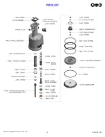
background image

8


12/21 REV 8/22


GB704SH

-

5 PNEUDRAULIC INSTALLATION TOOL.

.


Image may not reflect actual tool


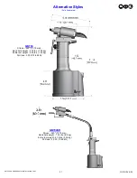
The tool is shipped with a red plastic plug in the air inlet connector. The connector has a 1/4

-

18 female pipe thread to accept user air 

hose fitting. The tool comes with oil and is ready to use.


1.  Remove red plastic shipping plug from Swivel (A

-

249) (air inlet) and screw in your quick disconnect (air) fitting.


 2.  Attach Deflector (200232) to rear of head cylinder assembly (704182). Rotate deflector (200232) away from operator or other people 


      working in the vicinity.


   3. Connect tool to air hose with 90 psi. (6.2 bar) using clean, dry air. 

3/8” (9.52 

mm) minimum diameter air line is recommended. 

Cycle tool five times by depressing and releasing lever (704345).


   4.  Disconnect air hose from tool.


   5.


Select proper nose assembly (see nose assembly selection chart on pg. 20 for more information). Screw collet onto piston and slide 

anvil over collet and secure with jam nut (70820). (See proper data sheet for further instructions).


   6.


Connect air supply.


HOW TO SET

-

UP THE GB704SH

-

5


FASTENER


WORK


NOSE ASSEMBLY


LEVER


HEAD CYLINDER ASSEMBLY


AIR INLET 


RED SHIPPING 

USER QUICK


DISCONNECT FITTING


AIR HOSE


WARNING:


Only qualified and trained operators shall install, adjust or use the assembly power tool for non

-

threaded 


       mechanical fasteners. 


WARNING: 

Operator 

MUST 

read and understand all warnings and cautions.


WARNING: 

It is required that eye protection, hearing protection and safety boots be worn at all times while handling this 

equipment.


WARNING: 

The users or the user

s employer must assess specific risks that could be present as a result after each use 


        based on their application. 


●  

Ensure there is adequate clearance for tool and operator's hands before proceeding. Keep fingers clear of any 


moving parts. Keep fingers clear from fasteners and installed materials. Severe personal injury may result.


●  

Verify 

the air lines and/or hydraulic hoses are not a trip hazard.


●  

Ensure that there are no electrical cables, gas pipes, etc., which can cause a hazard if damaged by the tool.


WARNING: 

Do not actuate fastener in the air. Personal injury from fastener ejecting may occur.


WARNING: 

Air is exhausted from the bottom of the tool. Direct bottom of the tool (exhausted air) away from operator, other   


 persons working in the vicinity, foreign matter and liquid.


WARNING: 

Do not carry from hoses or use as a hammer.


WARNING: 

Do not use in explosive atmosphere.


WARNING: 

Ensure air hose is securely connected to avoid possible hose whipping.


WARNING: 

Always disconnect air supply when tool is not in use to prevent accidental start

-

up.


WARNING: 

Ensure there is adequate clearance for tool and operator hands.


WARNING: 

Do not operate this tool without deflector, pintail catcher bag or pintail collection bottle in place.


CAUTION: 


Do not use beyond the design intent.


Summary of Contents for GBP704FSH

Page 1: ...ILT TOOLS ARE AVAILABLE WORLWIDE E MAIL US FOR A DISTRIBUTOR NEAR YOU ORIGINAL INSTRUCTIONS 44766 Centre Court Clinton Twp MI 48038 USA Ph 1 586 226 1500 Fax 1 586 226 1505 solutions gagebilt com www...

Page 2: ...cription and Technical Specifications 4 Description of Functions 5 Safety Warnings 6 Principle of Operation 7 How to Setup the GB704SH 5 8 How to use the GB704SH 5 9 Maintenance 10 Filling and Bleedin...

Page 3: ...faulty workmanship or material for 1 year from date of shipment Said warranty to remain in effect if and only if such goods are used in accordance with all instructions as to maintenance operation and...

Page 4: ...llation of blind fasteners They can be operated in any position They have a rated pull load of 3 300 lbs 14 68 kN with 90 psi 6 2 bar air pressure at the air inlet The GB704SH 5 and GB704SR installati...

Page 5: ...2 GB704SH 5 PNEUDRAULIC INSTALLATION TOOL DESCRIPTION OF FUNCTIONS Lever Handle Air Inlet Head Cylinder Assembly Deflector Image may not reflect actual tool Handle Assembly Hanger Hydraulic hose PULL...

Page 6: ...tted 10 Due to the tool weight it is recommended safety shoes be worn during operation 11 It is recommended tool be operated not more than 50 out of every 60 minutes where prolonged use is expected RE...

Page 7: ...e head cylinder assembly causing the piston to move to the rear of the head cylinder assembly The internal components of the attached nose assembly are also moving with the piston to start the fastene...

Page 8: ...s WARNING Operator MUST read and understand all warnings and cautions WARNING It is required that eye protection hearing protection and safety boots be worn at all times while handling this equipment...

Page 9: ...Ensure there is adequate clearance for tool and operator s hands before proceeding Keep fingers clear of any moving parts Keep fingers clear from fasteners and installed materials Severe personal inju...

Page 10: ...dirt Proper care by operators is necessary in maintaining full productivity and reducing downtime Keep nose assemblies especially jaws clean and free of chips and debris Lube jaws and collet surfaces...

Page 11: ...old handle 744303 to handle assembly 744129 keeping hydraulic hose A 122 towards plug 704313 located on handle assembly 744129 and torque button head cap screws A 928 to 40 inch lbs 4 52 Nm 4 Push pis...

Page 12: ...lace button head cap screw 402482 and stat o seal S572 and torque to 35 40 inch lbs 3 95 4 52 Nm Do not over tighten 8 Connect air supply Cycle tool ten times and check stroke of 600 15 24 mm using in...

Page 13: ...ter should be 028 71 mm Clear and size or replace 3 NO OPERATION WHEN LEVER 704345 IS DEPRESSED a Tool seized due to mechanical failure or damaged parts 4 OIL LEAKAGE a DO NOT OPERATE WITH OIL LEAKING...

Page 14: ...ove all rubber o rings seals wipers and hydraulic hoses All tool materials are recyclable except rubber o rings seals wipers and hydraulic hoses Dispose of rubber materials in accordance with the mate...

Page 15: ...it stops 2 Reinsert pin 703543 into hole on handle assembly 700343 3 Re attach the lever 704345 and tighten set screw 401771 Note View above shows proper orientation of lever POPPET VALVE WARNING Disc...

Page 16: ...44129 6 After removal of air piston assembly 744121 slide piston rod assembly 744136 back up to the end of its travel Using packing plug wrench assembly 704150 remove packing plug 744118 7 With packin...

Page 17: ...17 12 21 REV 8 22 GB704SH 5 PNEUDRAULIC INSTALLATION TOOL PARTS LIST...

Page 18: ...18 12 21 REV 8 22 GB704SH 5 PNEUDRAULIC INSTALLATION TOOL PARTS LIST...

Page 19: ...d when this material undergoes combustion ACCIDENTAL RELEASE MEASURES Protective Measures Eliminate all sources of ignition in vicinity of spilled material Spill Management Stop the source of the rele...

Page 20: ...8 704 16 GS8 704A 54RA GS8 704 40OS 10 32 GS10 704A 19 GS10 704 54RA GS10 704A 40OS STRAIGHT 1 INSTALLS 1 8 5 32 AND 3 16 DIAMETERS 2 RIGHT ANGLE NOSE ASSEMBLIES MAY REQUIRE MORE THAN ONE PULL 3 FRONT...

Page 21: ...ve Styles Sold Separately GB704 Stroke 540 13 72 mm Hand held weight 4 30 lbs 1 95 kg Entire tool weight 4 30 lbs 1 95 kg Pull load 3 300 14 68 kN GB704SR Stroke 540 13 72 mm Hand held weight 1 50 lbs...

Page 22: ...assembly for Cherrymax and High Clinch rivets Sold Separately L Part Number Equivalent to 2 704002 704A12 2 4 704004 704A12 4 6 704006 704A12 6 12 704012 704A12 12 Fill Bottle 745263 Sold Separately G...

Page 23: ...23 12 21 REV 8 22 GB704SH 5 PNEUDRAULIC INSTALLATION TOOL This page intentionally left blank...

Page 24: ...old Separately DEXRON IS A REGISTERED TRADEMARK OF GENERAL MOTORS CORPORATION LUBRIPLATE IS A REGISTERED TRADEMARK OF FISKE BROTHERS REFINING LOCTITE IS A REGISTERED TRADEMARK OF HENKEL CORPORATION TE...

Reviews: