Gage Bilt GB512BOM Original Instructions Manual Download Page 12

12


REV 12/22


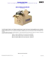
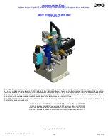
GB512BOM/GB512ABOM INSTALLATION TOOL


• 

Note: Gage Bilt does not recommend using a pneumatic lubricator or adding pneumatic oil to the air inlet on our tools or powerunits. 


OVERHAUL


WARNING

:  

Only qualified and trained personnel shall perform overhaul. 


WARNING

:  

Personnel must read and understand all warnings and cautions. 


WARNING

:  

Tool must be maintained in a safe working condition at all times and examined on a daily basis for damage or 


wear. Any repair must be done by qualified personnel trained on Gage Bilt procedures.


WARNING

:  

Disconnect tool from its power source before performing overhaul. Severe personal injury may occur if power 


  source is not disconnected.


WARNING

:  

Excessive contact with hydraulic oil and lubricants must be avoided. (See safety data sheet documents for all 


  applicable materials).


WARNING

:  

When operating, repairing or overhauling tool, wear approved eye protection. Do not look in front of tool or 


rear of tool when installing fastener. 


WARNING: 


Use only Gage Bilt hydraulic hoses and couplings, or equivalent, rated for 10,000 psi. (689.5 bar) working pressure.


WARNING: 


Ensure air hose is securely connected to avoid possible hose whipping (Air Actuated Tools only).


WARNING:


Do not exceed the maximum relief

-

valve setting stated on the tool and manual.


WARNING:


Relief valve must be installed with four flats towards the rear of the cylinder.


If a tool is performing poorly or leaking, a complete overhaul may be necessary.


Perform overhaul in a clean, well lit area using care not to scratch or nick any smooth surface that comes in contact with an o'ring. 

Use of Lubriplate® #630

-

AA (Gage Bilt part no. 402723) or equivalent during reassembly to prevent tearing or distorting of o'rings.


1.  Disconnect electric cord (206136) / air line (208126) from power supply. 


2.  Disconnect hydraulic hoses (206119) from power supply. 


3.  Remove hydraulic coupler

-

male (585047) & hydraulic coupler

-

female (585038) from hydraulic hoses (206119) and drain into a 


container. Remove nose assembly.


4.  Push piston assembly (512304) rearward until remaining hydraulic oil is drained. Push piston back to the front of cylinder 


assembly (205103). 


5.


Unscrew socket head cap screw (206118) from retaining ring (208117) using a spanner wrench to remove retaining ring. 


6.


Push piston assembly (512304) back until cylinder cap assembly (208115) falls out of cylinder assembly (205103).


7.


Continue pushing piston assembly (512304) rearward until piston assembly (512304) is out of cylinder assembly (205103). 


Remove relief valve (208110) from the piston assembly (512304). 


8.


Remove all O

rings and Back

-

up rings. Clean parts in mineral spirits or other o'ring compatible solvent being sure to clean 


o'ring grooves. Inspect components for scoring, excessive wear or damage. 


9.  Reassembly sequence is opposite of disassembly. Be sure relative positions of o'rings and back

-

up rings are as shown in 


exploded view and part list. When reinstalling relief valve (208110), be sure flats are to rear of tool (see pg. 11).


Coat hose fitting threads with a non

-

hardening Teflon thread compound such as Slic

-

tite®. DO NOT USE TEFLON® TAPE.


(

See hydraulic thread preparation pg.10)

.


Apply hot glue to wire connections of the electric actuator (240122) to ensure wires DO NOT contact each other. (Electric actuated 

installation tool GB512BOM only).


TOOL DISPOSAL


1.


When tool life is met, drain hydraulic oil from tool and dispose of the hydraulic oil in accordance with the safety datasheet.


2.


Disassemble tool and remove all rubber o

rings, seals, wipers and hydraulic hoses. All tool materials are recyclable except rubber 

o

rings, seals, wipers and hydraulic hoses. Dispose of rubber materials in accordance with the material safety datasheet. 


Note: 


• 

Dispose of hydraulic oil in accordance with manufacture safety datasheet.


• 

All tool materials are recyclable except rubber o

rings, seals and wipers.


• 

Use of SERVICE KIT (208100), which contains a complete set of o'rings, back

-

up rings and screws, can achieve 

a complete overhaul.


Summary of Contents for GB512BOM

Page 1: ...E MAIL US FOR A DISTRIBUTOR NEAR YOU GB512BOM GB512ABOM INSTALLATION TOOL ORIGINAL INSTRUCTIONS 44766 Centre Court Clinton Twp MI 48038 USA Ph 1 586 226 1500 Fax 1 586 226 1505 solutions1 gagebilt com...

Page 2: ...nty 3 Description and Technical Specifications 4 Description of Functions 5 Warnings 6 Principle of Operation 7 How to set up the GB512BOM GB512ABOM 8 How to use the GB512BOM GB512ABOM 9 Maintenance 1...

Page 3: ...r replacing defective goods or if the goods covered by this warranty are reworked or subjected to any type of additional processing This warranty is void if Seller is not notified in writing of any re...

Page 4: ...they have a built in nose assembly which helps in limited clearance areas These tools can be operated in any position They have a 750 19 1mm setting stroke and rated pull load of 10 000 lbs 44 5 kN Th...

Page 5: ...5 REV 12 22 GB512BOM GB512ABOM INSTALLATION TOOL DESCRIPTION OF FUNCTIONS Hydraulic Hose Pull Hydraulic Hose Return Cylinder Assembly Optional Hydraulic Hose Return and Hydraulic Hose Pull Inlet Anvil...

Page 6: ...ol weight it is recommended safety shoes be worn during operation 11 It is recommended tool be operated not more than 50 out of every 60 minutes where prolonged use is expected REPETITIVE MOTIONS HAZA...

Page 7: ...nd pull the sheets together The anvil is forced over the collar swaging it into locking grooves of the fastener Further force breaks the pintail off approximately flush with the collar When the piston...

Page 8: ...g WARNING Always disconnect air supply where applicable when tool is not in use to prevent accidental start up WARNING Do not exceed the maximum relief valve setting stated on the tool and manual WARN...

Page 9: ...of any moving parts Keep fingers clear from fasteners and installed materials Severe personal injury may result Verify the air lines and or hydraulic hoses are not a trip hazard Ensure that there are...

Page 10: ...nd electrical connections are secure Tighten Replace or Repair if necessary See hydraulic thread preparation below Cycle the tool several times to assure there are no leaks during use Only use a hydra...

Page 11: ...ns Tighten threaded connections Do not use Teflon tape b Oil leaks from tool Determine source of leak and replace worn or defective o rings and back up rings 6 PINTAIL GROOVES STRIPPED DURING PULL STR...

Page 12: ...5047 hydraulic coupler female 585038 from hydraulic hoses 206119 and drain into a container Remove nose assembly 4 Push piston assembly 512304 rearward until remaining hydraulic oil is drained Push pi...

Page 13: ...13 REV 12 22 GB512BOM GB512ABOM INSTALLATION TOOL GB512BOM PARTS LIST...

Page 14: ...14 REV 12 22 GB512BOM GB512ABOM INSTALLATION TOOL GB512ABOM PARTS LIST...

Page 15: ...e inspection gages to certify correct swage installation Sold Separately Grip Gage GB105093 For NAS LOCKBOLTS and blind fasteners Sold Separately Accessories Approved for use on Gage Bilt CE installat...

Page 16: ...PULL 5400 5700 psi RETURN 2200 2400 psi The GB940 Hydraulic Powerunit is available separately or in kits including hydraulic quick disconnect couplers electrical connectors and hose cord kits in vario...

Page 17: ...The GB910 Hydraulic Powerunit is available separately or in kits including hydraulic quick disconnect couplers air connectors air lines and hydraulic hoses in various lengths GB910 12 includes the GB...

Page 18: ...and air control socket are included to attach the equipment hydraulic hoses and air control tube The GB912 Hydraulic Powerunit is available separately or in kits including hydraulic quick disconnect c...

Page 19: ...19 REV 12 22 GB512BOM GB512ABOM INSTALLATION TOOL This page intentionally left blank...

Page 20: ...EFINING CO SLIC TITE IS A REGISTERED TRADEMARK OF LA CO INDUSTRIES INC LOCTITE IS A REGISTERED TRADEMARK OF HENKEL CORPORATION CHERRY CHERRYMAX AND BOM ARE REGISTERED TRADEMARKS OF HOWMET AEROSPACE Ri...

Reviews: