background image


4. Application software instruction

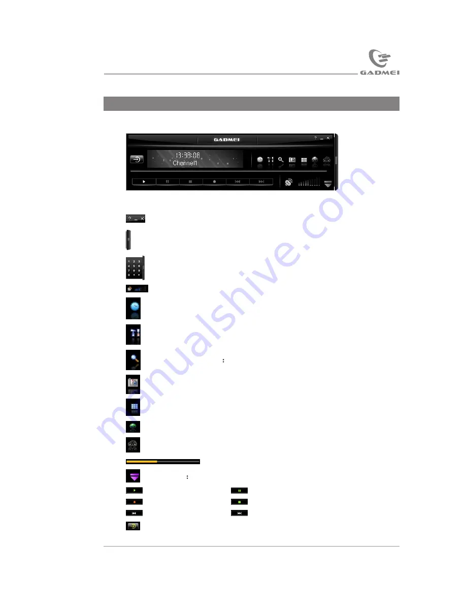
The main interface of the software, as below: 

Instruction for common keystrokes: 

Tuning box: Click to open or hide tuning box.

Digital input keystrokes: The left arrow is to decrease channels
and the right arrow is to increase channels. 

For adjusting volume: Drag mouse to quickly adjust volume. 

Scheduled recording setup: Click to open the scheduled recording 
                                               setting window. 

Function attribute: Click to open the attribute page.

Channel scanning

Click to access to channel scanning.

Picture capture: Click to capture static picture.

TV wall: For browsing channels.

Hyperlink to company website.

NICAM function keystroke (not available by this version). 

A/V files playing progress bar.

Favorite

Click to open or hide it. 

Play

Pause

Record

Stop

Fast backward

Fast forward

Input source switch: among TV, video1, video2 and S-Video. 

Consecutively perform the following operation: Open 

help

 file, 

minimize and close. 

12

15

Application software instruction

Click 

Software

 button to enter TVR PLUS installation interface, as 

the following picture:

The installation procedure will note you to select the desired language, 
and then click 

Ok

, as the following picture:

After automatic installation, the following picture will appear:

USB TV driver and software installation

Summary of Contents for UTV240

Page 1: ...User s Manual 240 240 2 4GHz Wireless TV Box ...

Page 2: ...Contents Contents ...

Page 3: ...rding function you will not miss any highlights High quality static picture capturing function converts every highlight into digital album and you can share with your friends via uploading to the web 1 Introduction 1 1 Brief introduction 1 2 Features There are 4 channels and the frequency scope ranges from 2 400GHz to 2 483GHz To increase the flexibility and reliability we prepare four selectable ...

Page 4: ... Large scale conference video system and multimedia teaching Security system real time spotwireless monitoring Introduction 1 1 3 Specifications TXV2408 wireless A Vtransmitter Power input DC 5V 300mA Radio frequency input 47 870MHz Video input 1Vp p PAL NTSC Audio input 2Vp p L R 2 4GHz channel Four channels 2414 2432 2450 2468MHz UTV324 wireless USB TVbox USB2 0 port Video input 1Vp p PAL NTSC A...

Page 5: ...ories UTV240 user s manual 1pcs Remote control 1pcs Power adapter 1pcs MMI AV cable 1pcs AV cable 1pcs MINI USB cable audio cable 1pcs Software disc 1pcs 1 7 Optional accessory MMI S Video cable DIN200S 1pcs Introduction ...

Page 6: ...Hz ANT Connection and operation 2 Connection and operation 2 1 UTV324 connection illustration Note Refer to Part4 software instruction to get UTV324 operation manual Antenna 2 2 TXV2408 connection illustration and panel operation instruction Rear panel Antenna Antenna Rear IR transmitting equipment ...

Page 7: ...rmally TV AV TV selected status TV AV AVselected status Note Receiver UTV324 input source selecting instruction Right click popup menu will be on UTV324 software interface when right m ouse down Select the item as picture below TV Switch to TV input of TXV2408 TV Composite 1 Switch toAV input of TXV2408 AV Composite 2 Switch to audioinput of UTV324 S Video Switch to S Video inputof UTV324 Connecti...

Page 8: ...e in the same channel can the A V signal be normally transmitted For example If select CH4 via the transmitter the CH 4 indicator is on meanwhileopen the software of the receiver right click the mouse and the right key menu will pop up Then select source selecting to switch to CH4 Now the receiver and the transmitter are sharing the same channel at thesame time as the picture below If wireless LAN...

Page 9: ...version first Automatic installation Connect UTV324 wireless USB TV box to the USB port of the host via USB cable place the software disc into the CD ROM driver the guide menu of installing the application software will automatically pop up If auto run function is terminated by your system you need to browse the disc and double click autorun exe the following picture will pop up Take Windows XP as...

Page 10: ...8 Click Next system installation as the following picture Click Finish USB TV driver and softwareinstallation ...

Page 11: ...ation After correctly install the hardware when power on to start Windows the system will detect new hardware noting Found New Hardware Wizard As thefollowing picture Select option3 and then click Next as the following picture USB TV driver and softwareinstallation ...

Page 12: ...tion2 and then click Next as the following picture Click Ok and then click Next as the following picture Click Browse to select the right saving path as the following picture USB TV driver and softwareinstallation ...

Page 13: ...LUS installation prior to installation of USB2 0 TV box software please install DirectX9 0 or higher version first Place the disc of GADMEI USB2 0 TV box software into the CD ROM driver and the installation guide menu of the application software will pop up If auto run function is terminated by your system you need to browse the disc and double click autorun exe the following picture will pop up U...

Page 14: ...ion interface as the following picture The installation procedure will note youto select the desired language and then click Ok as the following picture After automatic installation the followingpicture will appear USB TV driver and softwareinstallation ...

Page 15: ...Click Next as the following picture Click Browse to select the desired saving path and then click Next N as the following picture Click Next as below USB TV driver and softwareinstallation 13 ...

Page 16: ...ng thesoftware driver a small icon TTrayIcon will appear on the right down corner of your computer Make sure not to close the icon which is for remote control use If res tart TTrayIcon afterexiting please click Schedule TVin the driver installation list The TTrayIcon includes the following picture USB TV driver and softwareinstallation 14 ...

Page 17: ...ecording setting window Function attribute Click to open the attribute page Channel scanning Click to access to channel scanning Picture capture Click to capture static picture TV wall For browsing channels Hyperlink to company website NICAM function keystroke not available by this version A V files playing progress bar Favorite Click to open or hide it Play Pause Record Stop Fast backward Fast fo...

Page 18: ...n select video system according to the input source Note If the selected system does not go with the input source the image will be abnormal Input source Respectively TV video or S Video Video device Pleaseselect USB 2861 Device Audio device The default selection is the first audio device Audio playing Audioinput channel generally select Line In Audio recording Refer to audioplaying setup 4 2 Tuni...

Page 19: ...or better image effect via fine tuning Auto search Click to enter auto search stop when press again Sequencing Sequence manually 4 3 Video instruction Window scale Adjusting length and width scale when dragging the video window The default scale is any scale Image adjusting The user can adjust brightness contrast sharpness chroma and saturation according to his or her favorite Click default value ...

Page 20: ...ormation list 4 5 Other items Preview window When it is picture previewing the channel picture will pause on the screen for several seconds Previewing picture is to preview the number of channels Other options Video desktop not available for the current version Always on the top to display the playing window on the top If deleting previewing file after playing item is selected the file is to be de...

Page 21: ...Click Edit To modify any selected item Click Delete To delete the selected item Click All delete To delete all the itemsin the list Click Ok To exit the scheduled recordingwindow Click Cancel To exit the scheduled recordingwindow Click Setup to open scheduled recording item setting and then set the new item as below Application software instruction ...

Page 22: ...be automatically recorded After setting click OK to enter scheduled recording setting list Exit scheduled recording setting menu to finish setting Example demonstration If you want to schedule record programs of CATV 1 and the set scheduled recording time is 1 hour as below Note The scheduled recording time should not be the past time but should be the future time Click OK to show the following pi...

Page 23: ...ound will disappear when press for the first time and be normal when press again TV Input source switch to TV Note Connect TV cable to the input port of transmitter TXV2408 AV1 Input source switch to AV1 Note Connect video cable to the input port of transmitter TXV2408 AV2 Input source switch to AV2 Note Connect video cable to MMI AV input port of receiver UTV324 SV Input source switch to SV Note ...

Page 24: ... current signalinformation TV Wall Picture browsing Panel Hide or display themain interface Full Screen Enter or exitfull screen Attribute Hide or display thefunction attribute interface P Press this key toincrease channels when in TV status P Press this key todecrease channels when in TV status V Increase volume V Decrease volume Shortcut keys instruction Function Shortcut key Function Shortcut k...

Page 25: ...B watching Method one Use the front IRtransmitting device Put the transmitter onto the A V device and make sure IR transmitting sensor is 2 3 cm forward right towards the IR receiver sensor of the A V device Left view Front view STB DVD IR DVD remote sensor Note Generally there is infrared remote control or IR on the IR receiving sensor of STB or DVD please put the IR transmitting sensor towards i...

Page 26: ...V device Make sure no obstacles between them Vertical view Left view STB DVD STB DVD Note If permitted place like the above for better effects 6 2 UTV324 placing Follow the connection illustration to connect USB cable and then you can use UTV324 Make sure the IR sensor is right towards the remote control Product placing and retransmitting 2 4GHz AV Transmitter ...

Page 27: ...ot WIFI please adjust the 2 4GHzantenna for better effect 433MHz antenna using 2 Pay attention to the place of 433MHz antenna and make sure no obstacle around especially metallic obstacle which seriously affects signal retransmission Stretch out the antenna andplace as below Vertical view Right view Left view Rear view Product placing and retransmitting 2 4GHz AV Transmitter ...

Page 28: ...well connected and no obstacle between IR sensor of transmitter and that of video source Step two If the remote control is pointed towards UTV324 receiver you can operate the video source ofTXV2408 Note Please try to stretch out the 433MHz antenna of transmitter and put them far from the A V cable to make sure no transmission interruption If remote control is invalid please check the place of ante...

Page 29: ...ceiving distance 7 2 Using precautions 2 4GHz domestic appliance such as micro oven 2 4GHz cordless phone Bluetooth earphone or 802 11b g wireless network may affect the quality of receiving even cause no signals receiving If affected by micro oven the receiver should be put far from it As for other interruptions you can reset the signal channel of the transmitter and receiver The transmitter shou...

Page 30: ...ceiver refer to connection illustration Troubleshooting2 Remote control retransmission invalid Solutions Check whether the transmitter is right connected refer to connection illustration of transmitter Adjust the antenna place of transmitter and receiver refer to antenna placing Troubleshooting3 Image interrupted Change the transmission channel of receiver refer to channel selection Adjust the pla...

Page 31: ... NOTE THE MANUFACTURER IS NOT RESPONSIBLE FOR ANY RADIO OR TV INTERFERENCE CAUSED BY UNAUTHORIZED MODIFICATIONS TO THIS EQUIPMENT SUCH MODIFICATIONS COULD VOID THE USER S AUTHORITY TO OPERATE THE EQUIPMENT ...

Reviews: