Physical Characteristics
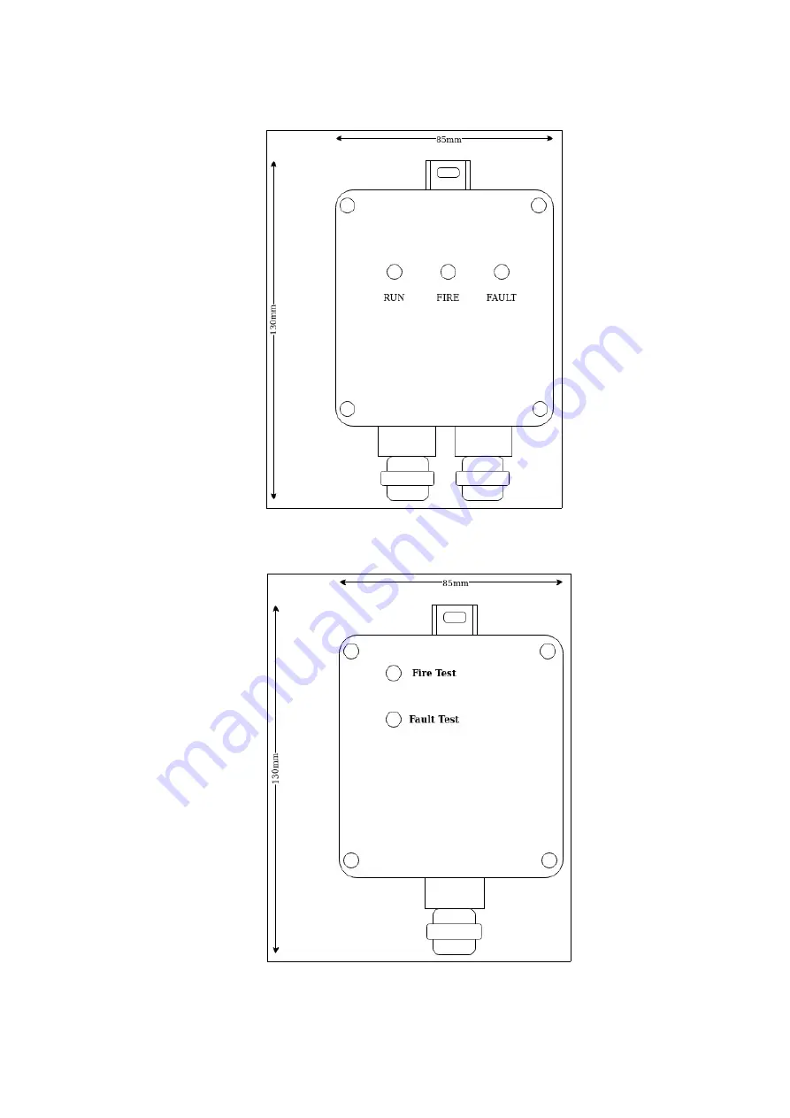
Diagram 1 – Physical Layout LHD-INT
Diagram 2 – Physical Layout LHD-EOL
LHD-INT & LHD-EOL Installation Guide
Page 3
Rev.1.7 ©G2 Security Pty Ltd
Page 1: ...with the LHDC supplied by PATOL The purpose of the 2 units is to act as an interface between the fire control equipment and the digital linear heat cable This allows for a flexible cable to be routed...
Page 2: ...ing Environment Relative Humidity 95 Protection class IP66 Dimensions Enc 90mm x 85mm x 52mm Overall Dimensions 130mm x 85mm x 52mm Table 1 General Specification LHD INT Model LHD EOL Operating Voltag...
Page 3: ...Physical Characteristics Diagram 1 Physical Layout LHD INT Diagram 2 Physical Layout LHD EOL LHD INT LHD EOL Installation Guide Page 3 Rev 1 7 G2 Security Pty Ltd...
Page 4: ...c power and the zone interface The LHD INT can be connected directly to a conventional fire panel zone and auxiliary power output or to an input interface from an addressable fire detection panel The...
Page 5: ...ected fire alarm equipment should also signal a fire condition Pressing the Fault Test button diagram 4 results in placing a simulated fault on the digital linear heat cable The corresponding LHD INT...
Page 6: ...g It will also indicate that it has triggered the fire event through to the fire control equipment FAULT This LED is only illuminated in the event of a fault condition or simulated fault condition fro...
Page 7: ...terminations be inspected Should these appear to be fault free then the digital linear heat cable should be removed from the termination and tested with a multi meter If this proves to provide unsati...