


49
y
y
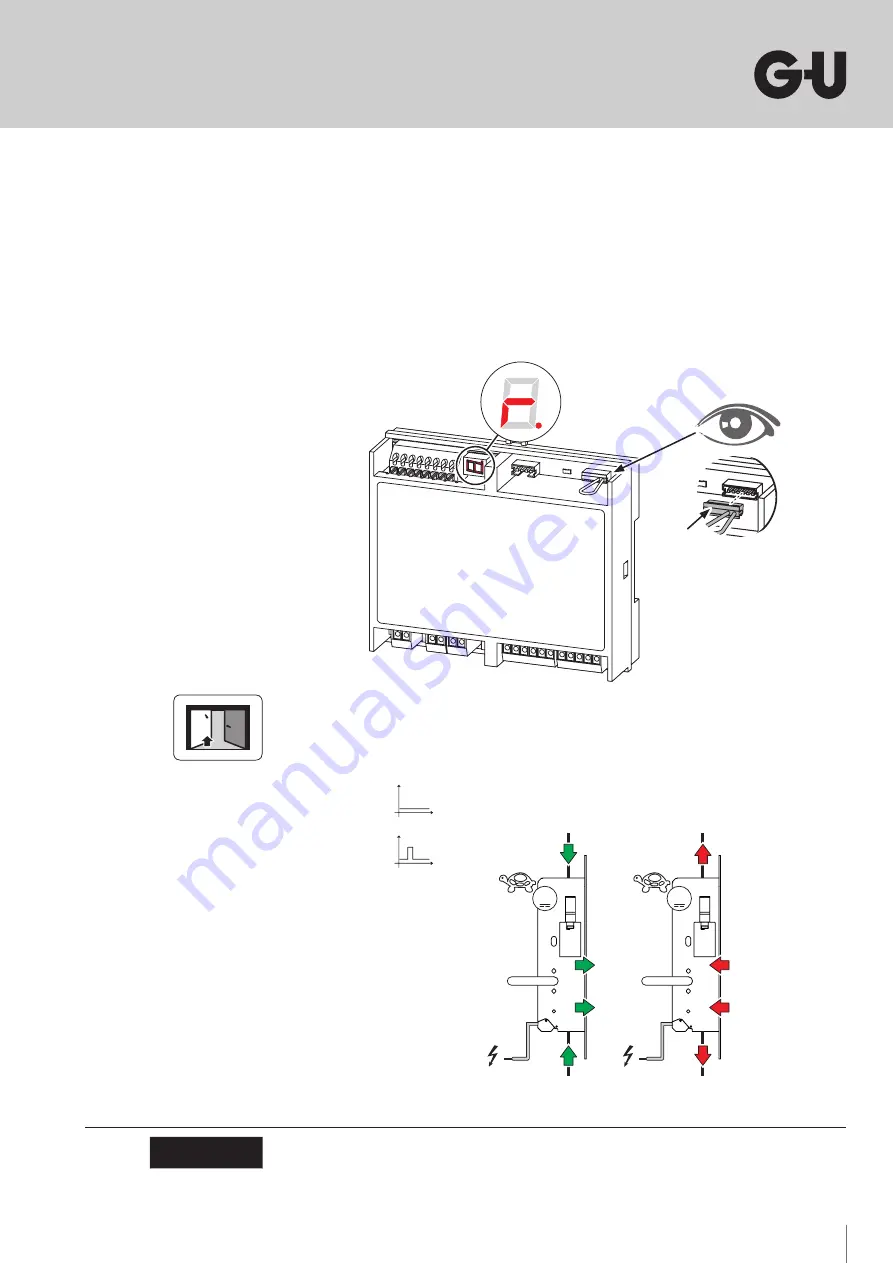
Once the power supply has been connected, the red LED at the controller lights up.
Make sure that the 6-pin service plug is inserted.
If an emergency power backup system B-54903-23-3-9 is also connected, the device starts
charging. While charging is in progress, the controller beeps rapidly until it is sufficiently charged
(max. 30 s). "R" indicates that the controller is ready.
y
y
Open both door leaves and make sure they cannot be closed accidentally.
y
y
Then trigger a
test run
via a control pulse at input I2. During this test, the lock moves through all
sensor points once thus testing that the wiring is correct.
Fig.5: Power supply
When making changes to or replacing individual components (controller B-54900-01-2-8,
motor-driven shoot-bolt lock B-2193x/B-2393x or connecting cable B 5490 0300/0308), you
must repeat the test run (see point 6.5)!
ATTENTION
Fig.6: Test run
I1:
I2:
24 V DC
M
24 V DC
M
Summary of Contents for B-54900-01-2-8
Page 141: ...141 ...
Page 143: ...143 1 2 3 4 ...
Page 146: ...146 B 2193x B 2393x 06 2019 22288S Designed in Germany Notizen Notes Notes Notas ...
Page 147: ...147 Notizen Notes Notes Notas ...