Page. 33
LM P RS485 Data Logger
8.3
M
ODBUS
ASCII
M
ESSAGE
F
RAMING
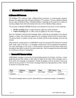
In ASCII mode, a message is delimited by specific characters as start of frames and end
of frames. A message must start with a
‘colon’ ( : )
character (ASCII 3A hex) and it ends
with a
‘carriage return – line feed’ (CRLF)
pair (ASCII 0D and 0A hex).
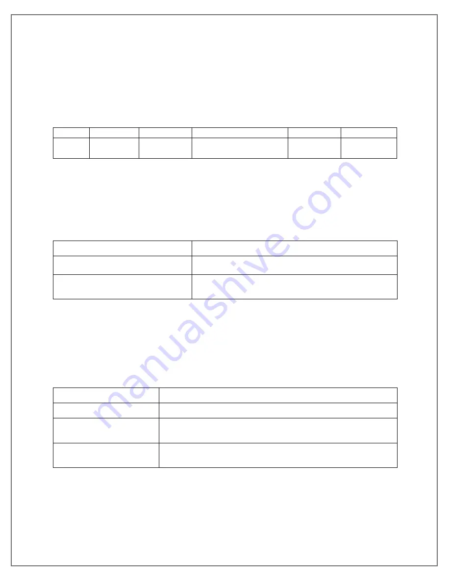
A typical message frame is shown below:
Start
Address
Function
Data
LRC
End
1 char
:
2 chars
2 chars
0 up to 2x252 char(s)
2 chars
2 chars
CR,LF
Each data byte needs two characters for encoding. The data size for ASCII data field is
double the maximum data size for RTU data field.
8.4
M
ODBUS FUNCTION CODES
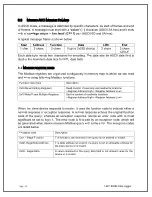
The Modbus registers are organized contiguously in memory map to which we can read
and write using following Modbus functions:
Function code (hex)
Description
0x03 Read Holding Registers
Read content of read only and read/write locations
<Register Address High> <Register Address Low>
0x10Write/Preset Multiple Registers
Set the content of read/write locations
<Register Address High> <Register Address Low>
When the slave device responds to master, it uses the function code to indicate either a
normal response or exception response. A normal response echoes the original function
code of the query, whereas an exception response returns an error code with its most
significant bit set to logic 1. The error code is followed by an exception code, which will
be generated when device receives Modbus query with some error. The exception codes
are listed below:
Exception code
Description
0x01 - Illegal Function
The function code received in the query is not allowed or invalid.
0x02- Illegal Data Address
The data address received in the query is not an allowable address for
the slave device or is invalid.
0x03 - Illegal Data
A value contained in the query data field is not allowed value for the
device or is invalid.
Summary of Contents for LM Pro 63 Series
Page 1: ......


