background image

g.tec medical engineering GmbH 

                g.USBamp, USB Biosignal Amplifier: Instruction for use 

____________________________________________________________________________________________________________________

V2.16.09 


Page 15 


Push-Pull Connectors 

g.USBamp connections on the rear side rely on highly reliable self-latching connectors based on the 

push-pull principle.  


Connecting a plug to the corresponding socket 


For connecting the self latching plug to the socket push the plug axially into the socket. 


Disconnecting a plug from a socket 


For disconnecting the plug from the socket pull on the outer release sleeves only. 


Attention:

 It is not necessary to use any tool for disconnecting the plug from the socket. 


Safe operation of g.USBamp 


Setting up g.USBamp 


Avoiding electrostatic discharge impulses to the safety input sockets: 

Electrostatic discharge (ESD) events can harm electronic components inside your device. Under  

certain conditions, ESD may build up on your body or an object, such as a peripheral, and then 

discharge into another object, such as the device. To prevent ESD damage, you should discharge 

static electricity from your body before you interact with any of your device. 

You can protect against ESD and discharge static electricity from your body by touching a metal  

grounded object (such as the potential equalization). When connecting the electrodes to the device 

you should always ground yourself to remove any static charge your body may have accumulated. 


To start g.USBamp for recording perform the following steps: 


Step 1:

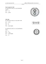
 Connect the medical power supply unit GTM21097-3005-5 with the POWER SUPPLY 

connector to the POWER SUPPLY socket of g.USBamp. 


Step 2:

 Connect the USB cable connector USB to the USB socket of g.USBamp and the PC USB 

connector of the cable to a USB connector of the PC. 


socket 

plug 

cable 

release sleeves 

Summary of Contents for g.USBamp

Page 1: ...7251 22240 0 Fax 43 7251 22240 39 office gtec at http www gtec at GlobTek power supply SN RoHS Instruction for use V2 16 09 Copyright 2017 g tec medical engineering GmbH printed Sept 2017 The product...

Page 2: ...__________________________________________________________________________________________________ V2 16 09 Page 2 How to contact g tec 43 7251 22240 0 Phone 43 7251 22240 39 Fax g tec medical enginee...

Page 3: ...nt side 10 Sockets connectors and switch on the rear side 11 5 Marking on the top side 12 6 Medical power supply GlobTek GTM21097 3005 14 7 USB cable 14 8 Push Pull Connectors 15 9 Safe operation of g...

Page 4: ...amp every time before using g USBamp check the device and its accessories for possible damages of connectors sockets and cables Cables connectors accessories or other parts of the equipment must be re...

Page 5: ...anufacturer is responsible for safety performance and reliability of the device under the condition as supplied to the customer at the time of delivery and a if changes are performed by the manufactur...

Page 6: ...must not be used in combination with any other medical high frequency device The usage of a high frequency device together with g USBamp can result in burnings under the electrodes and could damage t...

Page 7: ...nected directly to a PC or notebook with an USB connector without any additional data acquisition device needed 16 analog to digital converters perform the simultaneous sampling Each analog to digital...

Page 8: ...09 Page 8 Highlights EEG recording via USB 16 analog inputs with 24 Bit and 38 400 Hz sampling frequency per channel digital filtering of the biosignal data over sampling to achieve a high signal to...

Page 9: ..._________________________________________________________________________________________ V2 16 09 Page 9 3 g USBamp basic components g USBamp consists of the following items 1 g USBamp USB biosignal...

Page 10: ...ty sockets 9 12 4 analog input channels for EEG Push pull connector C is connected to safety sockets 9 12 Group D Safety sockets 13 16 4 analog input channels for EEG Push pull connector D is connecte...

Page 11: ...socket for the connection of the external power supply unit FUSE 1 6A 250V fuse type 20 mm quick acting potential equalization conductor SYNC OUT socket for the synchronization with another g USBamp S...

Page 12: ...p side do not dispose g USBamp with domestic waste Dispose it via the separate collection system for electrical and electronic equipment applied part of type CF follow instruction for use safety class...

Page 13: ...____ V2 16 09 Page 13 SN UB 2017 0 01 Serial number in the format UB Year_of_Production Month Number REF 0216US g tec product number code in the format xxxxxx EBCI7002US0 UB 2017 08 01N Human readable...

Page 14: ...l equipment g USBamp is the GlobeTek GTM21097 3005 It is a 5 V DC medical power supply unit If the medical power supply is connected to power line the green LED shows the correct operation of the devi...

Page 15: ...sockets Electrostatic discharge ESD events can harm electronic components inside your device Under certain conditions ESD may build up on your body or an object such as a peripheral and then discharg...

Page 16: ...be below 5 kOhm Step 5 Connect the electrodes to the sockets 1 16 to the reference and ground sockets of g USBamp Step 6 Switch on g USBamp with the switch on the rear side switch position ON The cor...

Page 17: ...ment In impedance measurement mode sequentially to each electrode an internally generated sine wave with 10 mV and 20 Hz is applied The voltage loss is measured and transmitted via USB to the PC NOTE...

Page 18: ...Page 18 Switching off and storage of g USBamp To switch off g USBamp and to store the device correctly please perform the following steps Step 1 Switch off the device with the switch on the rear side...

Page 19: ...conditions The device can be stored at temperatures between 20 to 60 degrees Celsius The relative humidity must be between 25 and 95 Wait before usage of the device till condensed water disappeared wa...

Page 20: ...sse 14 4521 Schiedlberg Austria Classification Safety class II Type of applied part CF Protection against mechanical distortion and liquids IP41 Operation mode S1 permanent operation The manufacturer...

Page 21: ...acting fuse type 20 mm Rated voltage of fuse 250 V Produced see serial number of g USBamp Producer g tec medical engineering GmbH Sierningstrasse 14 4521 Schiedlberg Austria http www gtec at Maximum...

Page 22: ...for analog channels there is a delay between the analog biosignal input and digital trigger input lines DRL and calibration output Digital analog Converter DAC DAC resolution 12 Bit Sampling frequency...

Page 23: ...ADC clock out Sensitivity 0 3 3 V ADC clock out Sensitivity 0 3 3 V Medical power supply Isolated medical power supply Rated power consumption 30 VA Rated AC voltage input 100 240 V Rated frequency 5...

Page 24: ...6 analog input 1 Pin assignment for the 6 pin socket B Pin 1 analog input 7 Pin 2 analog input 6 Pin 3 analog input 8 Pin 4 reference analog group B Pin 5 ground group B Pin 6 analog input 5 Pin assi...

Page 25: ...__________________________________________________________________________ V2 16 09 Page 25 Pin assignment for the 2 pin socket POWER SUPPLY Pin 1 5 V Pin 2 ground Pin assignment for the 4 pin socket...

Page 26: ...al input 2 Pin 4 digital input 3 Pin 5 digital output 0 Pin 6 digital output 1 Pin 7 ground digital Pin assignment for the 7 pin socket DIGITAL I O 2 Pin 1 digital input 4 Pin 2 digital input 5 Pin 3...

Page 27: ..._______________________________________ V2 16 09 Page 27 Power supply unit cable Pin assignment for the 2 pin connector POWER SUPPLY Pin 1 5 V Pin 2 ground USB cable Pin assignment for the 4 pin conne...

Page 28: ...medical engineering GmbH are to be used for this device Using third party manufacturer accessories may result in increased emission or decreased functional immunity of g USBamp As electric and magneti...

Page 29: ...an environment Emission test Compliance Electromagnetic environment guidance RF emissions CISPR 11 Group 1 The g USBamp uses RF energy only for its internal function Therefore its RF emissions are ve...

Page 30: ...ty should be that of a typical commercial or hospital environment Surge IEC 61000 4 5 1 kV differential mode 2 kV common mode 1 kV differential mode 2 kV common mode Mains power quality should be that...

Page 31: ...is the recommended separation distance in metres m b Field strengths from fixed RF transmitters as determined by an electromagnetic site survey a should be less than the compliance level in each frequ...

Page 32: ...maximum output power of the communications equipment Rated maximum output power of transmitter W Separation distance according to frequency of transmitter m 150 kHz to 80 MHz P V d 1 5 3 80 MHz to 80...

Reviews: