10
Do not allow the cable to become knotted or kinked.
Place the battery pack into the charger base.
(Note the battery has raised ribs which allows it to fit
into the charger only one way). Time the charge for 60
minutes only.
The red LED on the front right hand side of the
charger will illuminate to indicate charging is in
progress. A green LED will illuminate when the battery
is fully charged.
Unplug the charger when not in use and store it in a
suitable storage cabinet.
Avoid charging your battery in freezing conditions as
charging power will not be sufficient.
When charging more than one battery pack in
succession allow at least 30 minutes for the charger
to cool down before charging an additional battery.
Always remove the battery pack and store it safely
when the tool is not in use.
Caution: If at any point during the charging process
none of the LEDs are lit, remove the battery pack from
the charger to avoid damaging the product. DO NOT
insert another battery.
ASSEMBLY
INSTALLING JIGSAW BLADES
Selecting the correct type of blade is important in
order to obtain the best performance from the saw.
Select the blade based on the application and on the
material you wish to cut. Selecting the right blade will
give you a smoother, faster cut and prolong the life of
the blade.
The toolless blade changing system eliminates the
need for tools when installing or changing a blade.
Note: Before attaching a blade please ensure that the
battery is not connected to the jigsaw.
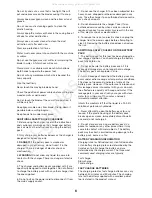
To fit the blade, push the quick change blade clamp
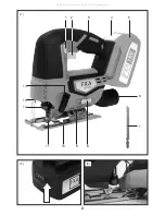
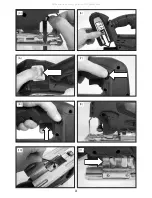
lever until it stops, Fig 3.
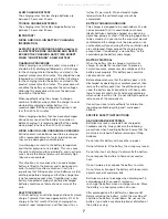
Holding the blade clamp lever in the open position,
insert the saw blade as far as possible into the slot in
the saw bar, Fig 4.
Check to make sure the back of the saw blade is
centered in the groove of the roller guide.
Release the blade clamp lever. Make sure the blade is
securely in place.
Note: During use periodically check the security of the
blade.
INSTALLING ThE BATTERY PACK
Warning!
Always remove battery pack from your tool
when you are assembling parts, making adjustments,
cleaning, carrying, transporting or when not in use.
Removing battery pack will prevent accidental starting
that could cause serious personal injury.
NOTE: To avoid serious personal injury, always
remove the battery pack and keep hands clear of the
lock-out button when carrying or transporting the tool.
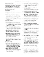
Slide the battery pack into the tool base, Fig.5. (Note
the battery has raised ribs which allows it to fit into
the pole saw only one way). Make sure the battery
pack snaps into place and that battery pack is
secured in the tool before beginning operation.
Improper installation of the battery pack can cause
damage to internal components.
REMOVING ThE BATTERY PACK
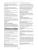
Locate the battery release catch on the top of the
battery and press downwards, Fig.6. Whilst holding
down the battery release catch slide the battery pack
away from the tool.
OPERATION
TURNING ThE JIGSAW ON & OFF
To turn the jigsaw ON, depress the lock-off safety
button, Fig 7 and then depress the On/Off switch,
Fig 8.
Release the On/Off switch to turn the jigsaw OFF.
VARIABLE SPEED CONTROL
Simply apply light pressure to the trigger to start the
jigsaw on a slow speed. Increasing the pressure on
the trigger will increase the speed of the jigsaw.
Note: You might hear a high pitched noise from the
trigger during use. Do not be concerned; this is a
normal part of the trigger function.
LED WORK LIGhT
Caution: Do not look in the light or see the source of
light directly.
Pull the On/Off trigger to light up the lamp. The lamp
keeps on lighting while the switch trigger is being
pulled. The lamp goes out immediately after releasing
the trigger.
ORBITAL MOTION
The blade of the jigsaw cuts in an orbital motion. This
feature is adjustable and provides faster, more efficient
cutting.
With orbital motion the blade cuts through your work
in the upstroke but does not drag across your work in
the downstroke. The higher settings should be used
when fast cutting in soft material is desired. The lower
settings should be used when cutting materials with
more resistance. The ‘0’ setting shuts off the orbital
motion. Setting ‘3’ offers the maximum orbital motion,
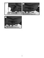
Fig 9.
ANGLE CUTTING (BEVEL CUTTING)
To set the cutting angle to one of the preset angles of
15°, 30°or 45°.
T TYPE BLADE
All manuals and user guides at all-guides.com


