


Section 40
00-02-0926
2016-07-27
- 3 -
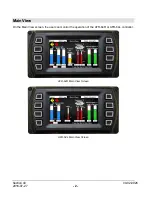
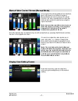
Staring at the top left corner of the Main View screen:
Engine Speed:
Actual engine speed is calculated by the number of pulses per revolution
entered by the user during the system setup.
Fault and Warning Indicators:
The yellow symbol is an indicator that the
fault relay has been activated and an active fault is present. The red symbol is
an indicator that the shut-down relay has been activated and a shut-down fault
is active.
O2 Sensor Phi Values:
These are the values read from the Left Bank, Right Bank and Post-
catalyst oxygen sensors and are used to determine the air-to-fuel ratio of the engine by
measuring the excess exhaust oxygen concentration. If the engine is set up for a single bank
application, the Right Bank sensor value will read OFF. If the post-catalyst oxygen sensor is
turned off, the Post-catalyst sensor field will also read OFF. Note: the AFR-64L does not
have post-catalyst sensors; therefore, the Main View does not show this.
Target Values:
These are the desired phi targets for pre-catalyst and post-catalyst control (if
equipped).
PreCat Phi Offset (AFR-64R only):
This value indicates the amount of offset that has been
applied to the pre-catalyst target to achieve the desired post-catalyst target. This value is
only active if the post-catalyst sensor is used.
MAT - Manifold Air Temperature (AFR-64L only):
The MAT gage shows the engine
’s
manifold air temperature.
Catalyst Temperatures:
The pre-catalyst and post-catalyst temperatures are displayed here
along with the calculated differential between the two (post-cat minus pre-cat). If the catalyst
thermocouples are not used, these values show ambient temperature inside of the
enclosure.
Valve Position:
These values are the commanded positions for the Left Bank and Right
Bank fuel control valves.
Mode:
This field will indicate whether the valve control is in Automatic or Manual. While in
automatic, the controller determines the valve position based on feedback from the oxygen
sensors. While in manual, the user determines the valve position. Manual valve control can
be accessed through the Main Menu. Note: Manual mode can only be entered while the
engine is running.
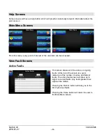
Press any button to access the Main Menu
Summary of Contents for AFR-64L
Page 4: ...THIS PAGE INTENTIONALLY LEFT BLANK...
Page 14: ...Notes...
Page 15: ...Notes...
Page 16: ......


