


TABLE 7.1 TROUBLESHOOTING
Sympton
Probable Causes (s)
Solution (s)
1) Keypad no function
- Bad connection between PCB & keypads
- Clean contact area on PCB
- Replace keypads
2) LED's will not light
- No power to instrument
- Power supply defective
- Check power line connections
- Replace power supply board
- LED display or LED Lamp defective
- Related LED driver defective
- Replace LED display or LED lamp
- Replace the related transistor or IC chip
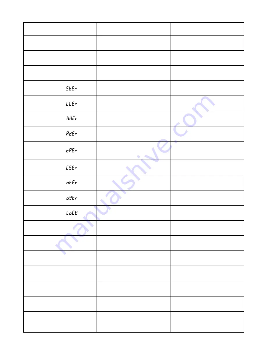
4) Process Display shows:
- Sensor break error
- Replace RTD or sensor
- Use manual mode operation
5) Process Display shows:
- Input signal beyond the low range, sensor fails
- Incorrect input type selected
6) Process Display show:
- Input signal beyond the high range,sensor fails
- Incorrect input type selected
7) Process Display shows:
- A to D module damage
8) Process Display shows:
9) Process Display shows:
- Check and reconfigure the control parameters
10) Process Display shows:
- Fail to enter data into EEPROM
- Replace EEPROM
11) Process Display shows:
12) Process Display shows:
- Attempt to change a locked parameter
- Unlock procedures stated in section 5.16
13) Display Unstable
- Analog portion or A-D converter defective
- Thermocouple, RTD or sensor defective
- Intermittent connection of sensor wiring
- Replace related components or board
- Check thermocouple, RTD or sensor
- Check sensor wiring connections
14) Considerable error in temperature indication
- Reversed input wiring of sensor
- Check and correct
16) No heat or output
- Check output wiring and output device
- Replace output device
- Replace output fuse
- Check and replace
18) Control abnormal or operation incorrect
- Check and replace
- Read the operation procedure carefully
- Overflow error, data out of range during
execution of software program
- Wrong sensor or thermocouple type. Wrong
input mode selected.
- Analog portion A-D converter defective
- Replace sensor
- Check sensor or thermocouple type, correct
input selection
- Replace module. Check for outside source of
damage such as transient voltage spikes.
- Repeat procedure. Increase Prop. Band to a
number larger than 0.
- Increase proportional band
- Check if there is a noise comming in. Solve
the problem by means of item (19).
3) Some segments of the display or LED lamps
not lit or lit erroneously.
- Check sum error, values in memory may have
changed accidentally
- Incorrect operation of auto tune procedure.
Prop. Band set to 0
- Manual mode is not allowable for an ON-OFF
control system
- Replace sensor
- Check sensor or thermocouple type, correct
input selection
17) Heat or output stays on but indicator reads
normal
- CPU or EEPROM (non-volative memory)
defective. Key switch defective
- Operation of control incorrect
- Output device shorted, or power service
shorted
19) Display blinks, entered values change by
themselves
- Electromagnetic interference (EMI), or Radio
Frequency interface (RFI)
- EEPROM defective
- Suppress arcing contacts in system to eliminate
high voltage spike sources. Separate sensor
and controller wiring from " dirty" power lines,
ground heaters
- Replace EEPROM
- No heater power (output), incorrect output
device used
- Output device defective
- Open fuse outside of the instrument
15) Display goes in reverse direction ( counts
down scale as process warms)
- Check sensor or thermocouple type and if
proper input mode was selected
- Replace related components or board
Page 13


