Future Design FDC-9200 User Manual Download Page 10

5.9  COOLING  CONTROL

Cooling Control Options:

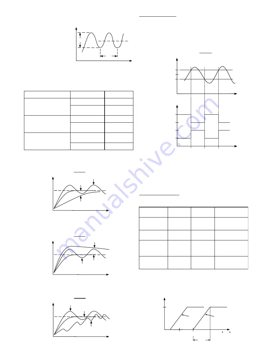
Functions of CPB and DB:
The cooling P band CPB and dead band DB are measured in degree.

(2) The cycle time (T) of this oscillation in seconds (see following Figure).

* The control setting should then be adjusted as follows:

PB = P (°C or °F)

TI  = T (seconds)

TD = T/4 (seconds)

The PID parameters determined by the above procedures are just rough
values.  If the control results by using above values are unsatisfactory, the
following rules may be used to further adjust the PID parameters:

5.8  ON-OFF  CONTROL

The alarm output if configured as alarm function performs an ON-OFF
control  basically.   Adjust the P band to PB = 0,  an additional channel of
ON-OFF control with variable hysteresis is obtained.  Hysteresis is
measured with degree.  It is also named differentials or deadband
sometimes.  Refer to following Figure for the description of ON-OFF control.

ON-OFF  control may introduce excessive process variation even if the
hysteresis is minimized to the smallest.  If the ON-OFF control is set,
parameters TI, TD and CCT will have no effect on the system, nor can the
manual mode and the auto-tune program be executed.

PV

Time

D action

Perfect

TD too high

TD too low

SP

PV

Time

Time

P action

SP

100%

0%

100%

0%

Reverse

Action

Action

(CONA=REVR)

(CONA=DIR)

Direct

OUTPUT

SP+HYST/2

SP-HYST/2

SV+DB

CPB

SV

DB

Negative

DB

Positive

100%

0%

Cooling

Output

PV( C or F)

P

T

SV

PV

Time

PV

Time

P action

Perfect

PB too high

PB too low

SP

PV

Time

I action

Perfect

TI too low

TI too high

SP

Effect of PID adjustment on process response:

ADJUSTMENT SEQUENCE

SYMPTON

SOLUTION

(1) Proportional Band (P)

Slow Response

    Decrease PB

             PB

High overshoot or
Oscillations

    Increase PB

(2) Integral Time (I)

Slow Response

    Decrease TI

             TI

Instability or
Oscillations

    Increase TI

(3) Derivative Time (D)

Slow Response or
Oscillations

    Decrease TD

             TD

High Overshoot

    Increase TD

Output

Configurations

Heating Output

Cooling Output

Adjustment of

Parameters

ON-OFF Cooling
( No Heating)

None

OUT1

CONA = DIRT
HYST
SV

Proportional Cooling
( No Heating)

None

OUT1

CONA = DIRT
PB, TI, TD, CYC, SV

H
ON-OFF Cooling

OUT1

ALM2

CONA = REVR
A2SF = NONE
A2MD = DVHI (or FSHI)
AHY2, SV (or ASP2)

H
Proportional Cooling

OUT1

ALM2

CONA = REVR
A2SF = COOL
CPB, DB, CCYC, SV

Page 9

Summary of Contents for FDC-9200

Page 1: ...User s Manual FDC 9200 Self Tune Fuzzy PID Process Temperature Controller...

Page 2: ...although PID control has been used and proved to be an efficient controlling method by many industries yet the PID is difficult to deal with some sophisticated systems such as second order systems lon...

Page 3: ...Band Reset Integral Rate Derivative Ramp Rate Dwell ON OFF Cycle Time Control Action POWER Rating Consumption ENVIRONMENTAL PHYSICAL Safety Protection EMC Emmission EMC Immunity Operating Temperature...

Page 4: ...larity is observed throughout Joints in the cable should be avoided if possible The colour codes used on the thermocouple extension leads are shown in Table 4 1 4 4 5 Relay Output Direct Drive Figure...

Page 5: ...C 3 Silicon Rubber buttons For ease of control set up and setpoint adjustment Control Output Setpoint Value Alarm Outputs Process Value 3 5 7 4 6 8 or or Alarm 2 Control Output 2 Alarm1 Output Control...

Page 6: ...Hold Function Dwell Timer ON as Time Out No Special Function Alarm with Latch Function Alarm with Latch Hold Function Dwell Timer OFF as Time Out Deviation High Alarm Full Scale High Alarm Full Scale...

Page 7: ...compensatio Adjust the drift compensation code 6 6 6 6 count Select a proper status for Output 1 Output 1 ON Output 1 OFF Select Lock or F ree for the Security Level 0 Protect Lock all the Level 0 pa...

Page 8: ...be added to the process value so that the process value will be read with minimum error For those process with bad circulation may use this parameter to compensate the temperature difference between...

Page 9: ...r that parameter by using up key or down key Finally press and hold 3 2 seconds or longer now the new level value is entered If the level value is unchanged the above operation for entering can be omi...

Page 10: ...is set parameters TI TD and CCT will have no effect on the system nor can the manual mode and the auto tune program be executed PV Time D action Perfect TD too high TD too low SP PV Time Time P action...

Page 11: ...e to be used An error message will be shown in the display The manual control is used during Teaching the process The controller fails The manual control is an open loop control The process may rise t...

Page 12: ...enabled by configuring the alarm 1 to act as a dwell timer If A1SF is set to time out on the alarm 1 relay will now operate as a timer contact with the contact being opened on initial start up The ti...

Page 13: ...procedure connect a thermocouple to terminal 13 and 14 observing polarity and select a correct INPT for the thermocouple Switch the power on and let the controller to be powered for at least 30 minut...

Page 14: ...Control abnormal or operation incorrect Check and replace Read the operation procedure carefully Overflow error data out of range during execution of software program Wrong sensor or thermocouple typ...

Page 15: ...ermocouple type wrong input mode selected Analog portion of A D converter defective Check sensor or thermocouple type and if proper input mode was selected Replace related components or board Reversed...

Page 16: ...User s Manual FDC 9200 Process Temperature Controller 7524 West 98th Place Bridgeview IL 60455 Phone 888 751 5444 Fax 888 307 8014...

Reviews: