background image

5.6  AUTO-TUNE

              The process is tuned at setpoint.  The process will oscillate about
the setpoint during auto-tune.  Set a setpoint to a lower value if overshoot
beyond the normal process value is likely to cause damage.

The auto-tune program is applied during:
* Initial set-up
* The setpoint is changed substantially from the previous auto-tune
* The control result is unsatsifactory

The auto-tune procedures:
* To ensure that all parameters are configured correctly.
* To ensure that PB is not zero because that ON-OFF control is not allowable
   to perform auto-tune.
* Set the setpoint to the normal operating process value  ( or  to  a  lower
   value if overshoot beyond the normal process value is  likely  to  cause
   damage) and use normal load conditions.
* Press and hold both up and down keys for  3.2  seconds  then  release
   together.  The display is  flashing  during  execution of auto-tune
   program.

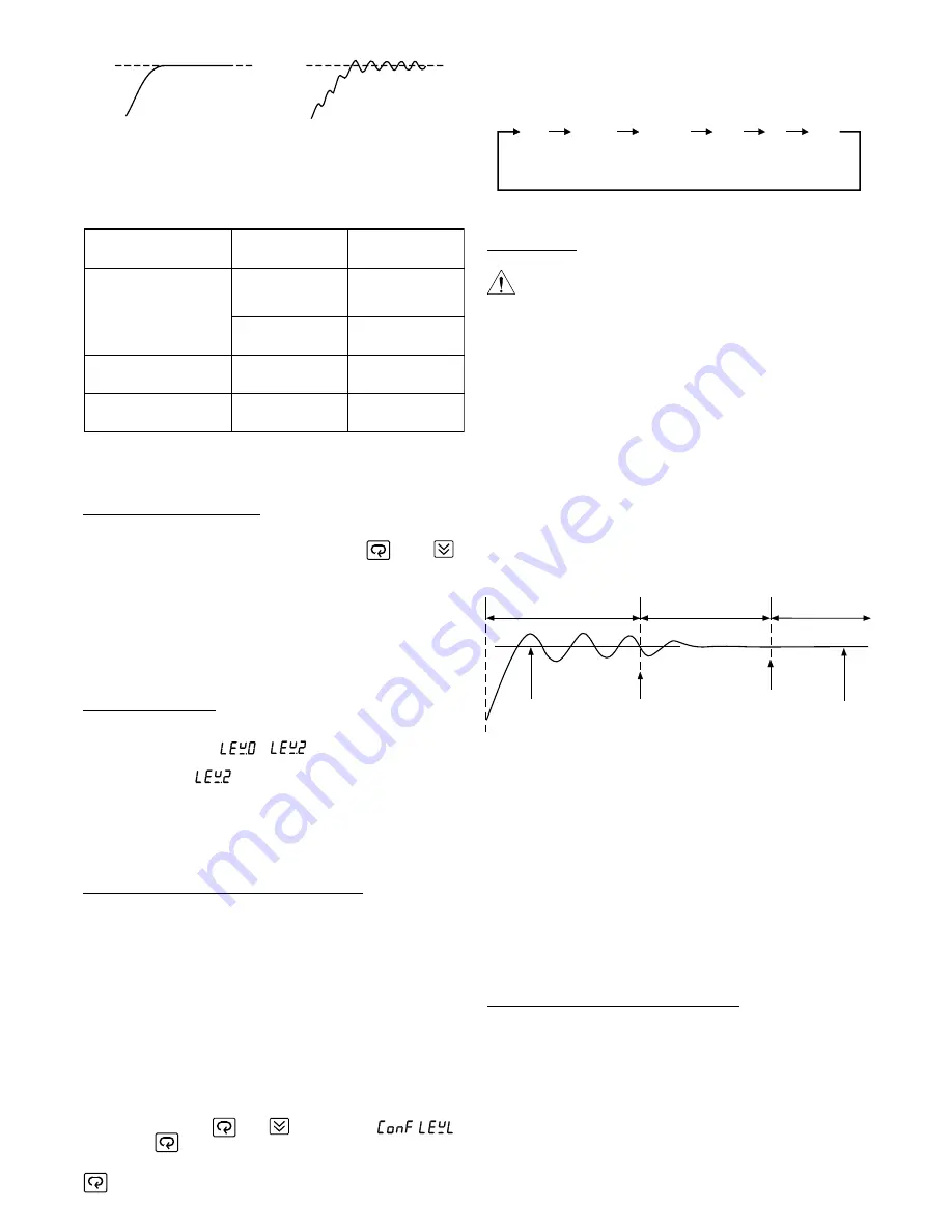
Auto-tune " teaches " the controller the main characteristics of the process.
It " learns" by cycling the output on and off.  The results are measured and
used to calculate optimum PID values which are automatically entered in
nonvolatile memory.

During the second period of auto-tune the controller performs  PID control
to verify the results and finally an OFST value is obtained and entered in
the memory.

To stop the auto-tune, press both up and down key then release together,
the display will stop to flash.   But if the controller has entered in the
verifying period, the display will continue to flash until auto-tune is finished.

5.5.5  Configure Security Levels of Parameters

The user of the controller may often complain that the operation is so
complicated, most of parameters are unused for them and it takes long time
to get a parameter to access.  You will no longer worry about this.  One of
the versatile functions of this controller is that the security level for each
parameter can be  redefined arbitrarily.  One of four levels (Level 0, Level
1, Level 2 and Level 3) can be assigned to any parameter.  The parameters
with lower level will be displayed before those parameters with higher
level as one performs scroll key.  Furthermore, the level 3 parameters will
never be displayed on the front panel.  Hence the user can assign level 3
to those unused parameters and assign level 0 to those most frequently
used parameters according to his requirements.  Then the unused
parameter will never appear on the display to avoid confusion and the
display sequence of parameters is reconfigured.

To configure level for each parameter one can follow the flow chart in
section 6.4 by pressing           and            keys to reach                           ,
then perform           key to get the desired parameter.  The display indicates
the level of the parameter.  Now one can change the level value for that
parameter by using up key or down key.    Finally press and hold
         3.2 seconds or longer, now the new level value is entered.  If the

level value is unchanged the above operation for entering can be omitted.
For example:  If ASP1, RAMP are configured as level 0, PB, TI, TD  are
configured as leve 1, and the other parameters are configured as level 3,
the scrolling sequence of  parameters will be as follows:

5.7  TUNING  THE  CONTROLLER  MANUALLY

* To ensure that all parameters are configured correctly
* Set PB to zero.  Set HYST to the smallest ( 0 °C or 0.1 °F )
* Set the setpoint to the normal operating process value ( or  to  a  lower
  value if overshoot beyond the normal process value is  likely  to cause
  damage) and use normal load conditions.
* Switch on the power supply to the heater.  Under these conditions, the
   process  value  will  oscillate  about  the   setpoint  and  the   following
   parameters should be noted:

(1) The peak to peak variation (P) of the  first  cycle in  °C or °F  ( i.e. the
     difference between the highest value of  the  first  overshoot and the
     lowest value of the first undershoot ).

Normal Cycle time

Cycle time too long

(oscillates)

The follow table provides cycle time recommendations to avoid premature
relay failure:

Note: For an ON-OFF control ( by setting PB = 0) the cycle time selection
         may be ignored.

Output Device

(OUT1 or Cooling  Output)

Cycle Time

( CYC or CCYC )

 Load ( resistive)

Relay

20 sec or more
recommended
10 sec. minimum

2A / 250VAC

or contactor

5 sec. minimum

1A / 250VAC

Solid State Relay Drive

1- 3 sec.

SSR

Linear Current / Voltage

0.1 sec.

Phase control module

5.5.3  FAIL-SAFE Configuration

FAIL-SAFE is a Tool Program used to define an ON or OFF status of failure
for Output 1 (OUT1),  Alarm 1 Output (ALM1).  Press              and             ,
then release both keys until FAIL-SAFE is viewed in the display windows.
Then press scroll key to obtain the desired output which is shown in the
display.  Now press and hold up or down  key to change the status which
is shown in the display.  Note that if the desired value is different from the
original one, a long scroll (pressing scroll key 3.2 sec.) has to be operated
to enter the new value before proceeding to the next Tool Parameter .  If
the FAIL-SAFE status is not critical for a process as the controller fails, the
configuration of this section can be omitted.

5.5.4  LOCK Parameter

According to the flow chart shown in section 6.4, one can reach LOCK
PARA and obtain LEVEL (              ~               ) which is shown in the display
and the Lock status ( LOCK or FREE ) is shown in the display.  For example,
if we select LOCK for            , and press scroll key 3.2 seconds to enter the
selection, then all the parameters configured in level 2 can not be changed.
A LOCK message will be indicated in display if one attemps to change a
locked (protected) parameter.

PID+FUZZY

Verifying period

PID Control

Teaching Period

ON-OFF Control

Setpoint

Value

PB,TI,TD

Obtained

Auto-tune

finished

OFST Value

Obtained

Process

Value

SV

ASP1

RAMP

PB

TI

TD

Page 8

Summary of Contents for FDC-2220

Page 1: ...User s Manual FDC 2220 Self Tune Fuzzy PID Process Temperature Controller ...

Page 2: ...dred years although PID control has been used and proved to be an efficient controlling method by many industries yet the PID is difficult to deal with some sophisticated systems such as second order systems long time lag systems during setpoint change and or load disturbance circumstance etc The PID principle is based on a mathematic modeling which is obtained by tuning the process Unfortunately ...

Page 3: ...FF Cycle Time Control Action POWER Rating Consumption ENVIRONMENTAL PHYSICAL Safety Protection EMC Emmission EMC Immunity Operating Temperature Humidity Insulation Breakdown Vibration Shock Moldings Weight 100 K ohms 0 1 C C ambient typical Protection mode configurable 100 ohms max 60dB 120dB 5 times second 0 200 C 0 360 F 0 3600 seconds 0 1000 seconds 0 55 55 C 99 99 F minute 0 9999 minutes With ...

Page 4: ...ration should be given to the prevention of unauthorised personnel from gaining access to the power terminations 4 4 2 Thermocouple Input Thermocouple input connections are shown in Figure 4 5 The correct type of thermocouple extension lead wire or compensating cable must be used for the entire distance between the controller and the thermocouple ensuring that the correct polarity is observed thro...

Page 5: ... 4 12 Linear Voltage Current Connections 6 5 _ 0 20mA 4 20mA or 0 10V 4 4 8 Linear Output There are three types of linear output modules See Section 2 can be selected for control output OUT 1 The connections are shown in Figure 4 12 6 5 Load 120V 240V Mains Supply _ _ SSR Fig 4 11 SSR Drive Connections TOUCHKEYS FUNCTION DESCRIPTION Up Key Press and release quickly to select the desired digit of a...

Page 6: ... Heating Action Alarm with Hold Function Dwell Timer ON as Time Out No Special Function Alarm with Latch Function Alarm with Latch Hold Function Dwell Timer OFF as Time Out Deviation High Alarm Full Scale High Alarm Full Scale Low Alarm Deviation Band High Alarm Deviation Band Low Alarm Deviation Low Alarm 5 3 FLOW CHART OF PARAMETERS Normal Display Process value setpoint value Low scale to high s...

Page 7: ...n code 19 9 42 7 count Adjust the drift Adjust the drift compensation code 6 6 6 6 count Select a proper status for Output 1 Output 1 ON Output 1 OFF Protect Lock all the Level 0 parameters Allow all the Level 0 parameters to be adjustable Select Lock or F ree for the Security Level 1 Protect Lock all the Level 1 parameters Allow all the Level 1 parameters to be adjustable Select Lock or F ree for...

Page 8: ...rocess value so that the process value will be read with minimum error For those process with bad circulation may use this parameter to compensate the temperature difference between sensor and the process PB TI TD Constants for PID Control Refer section 5 7 for an in depth description AHY1 Hysteresis Values of Alarm 1 These values define the dead bands for alarm action As the process value exceeds...

Page 9: ...or that parameter by using up key or down key Finally press and hold 3 2 seconds or longer now the new level value is entered If the level value is unchanged the above operation for entering can be omitted For example If ASP1 RAMP are configured as level 0 PB TI TD are configured as leve 1 and the other parameters are configured as level 3 the scrolling sequence of parameters will be as follows 5 ...

Page 10: ... is set parameters TI TD and CCT will have no effect on the system nor can the manual mode and the auto tune program be executed PV Time D action Perfect TD too high TD too low SP PV Time Time P action SP 100 0 100 0 Reverse Action Action CONA REVR CONA DIR Direct OUTPUT SP HYST 2 SP HYST 2 SV DB CPB SV DB Negative DB Positive 100 0 Cooling Output PV C or F P T SV PV Time PV Time P action Perfect ...

Page 11: ...le to be used An error message will be shown in the display The manual control is used during Teaching the process The controller fails The manual control is an open loop control The process may rise to a dangerous value temperature Special attention to the process has to be given to prevent a system damage 5 13 RAMP DWELL The controller can be configured to act as either a fixed setpoint controll...

Page 12: ...is enabled by configuring the alarm 1 to act as a dwell timer If A1SF is set to time out on the alarm 1 relay will now operate as a timer contact with the contact being opened on initial start up The timer begins to count down once the setpoint temperature is reached After the setting at ASP1 has elapsed the alarm 1 relay closes The dwell function may be used to operate an external device such as ...

Page 13: ...ration procedure connect a thermocouple to terminal 13 and 14 observing polarity and select a correct INPT for the thermocouple Switch the power on and let the controller to be powered for at least 30 minutes If the controller does not measure a correct temperature for the thermocouple the following procedures may be employed to correct the error 1 Perform procedure 1 and 2 stated in calibration p...

Page 14: ...8 Control abnormal or operation incorrect Check and replace Read the operation procedure carefully Overflow error data out of range during execution of software program Wrong sensor or thermocouple type Wrong input mode selected Analog portion A D converter defective Replace sensor Check sensor or thermocouple type correct input selection Replace module Check for outside source of damage such as t...

Page 15: ...hermocouple type wrong input mode selected Analog portion of A D converter defective Check sensor or thermocouple type and if proper input mode was selected Replace related components or board Reversed input wiring of sensor Check and correct 7 No heat or output No heater power output incorrect output device used Output device defective Open fuse outside of the instrument Check output wiring and o...

Page 16: ...User s Manual FDC 2220 Process Temperature Controller 7524 West 98th Place Bridgeview IL 60455 Phone 888 751 5444 Fax 888 307 8014 ...

Reviews: