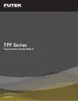
Futek TFF Series Manual Download Page 9

Power Supply

Shield

Jacket

Shield

Wires

TFF Torque Sensor Family Manual

9

Sensor Solution Source

Load · Torque · Pressure · Multi-Axis · Calibration · Instruments · Software

www.futek.com

Shield Usage and Connections

•  Cable shielding should be grounded on one 

end, either the sensor side or instrument 
side to avoid ground loops .

•  A shield connection listed as floating on a 

sensor’s spec sheet means the cable shield 
is not connected on the sensor side and may 
be connected on the instrument side  
to ground .

•  Shield connections are located  

on the sensor’s spec sheet .

Calibration

•  A yearly calibration is recommended .  But 

verification and calibration period shall be 
defined based on application, conditions, 
endurance and usage .

•  FUTEK offers NIST calibrations as well 

as A2LA certified calibrations for total 
uncertainty .

•  For more information on available 

calibrations visit FUTEK calibration web 
page at: 

http://www .futek .com/calibration-

services .aspx

•  For recalibration orders visit the FUTEK 

recalibration page at: 

http://www .futek .com/

recalibration .aspx

•  An online summary of calibration results 

is available at: 

http://www .futek .com/

calibrationData .aspx
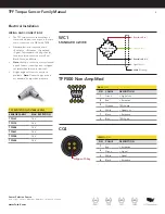
SHUNT

A shunt is an external resistance applied across 
two points on the load cell’s Wheatstone 
bridge to generate a known, fixed output from 
the sensor .

Shunt results can be used to set up instruments 
as well as compare changes to the load cell 
output over time and usage .

When selecting the appropriate shunt 
resistance for your load cell, we recommend a 
resistance that generates an output of about 
80% of the sensor’s rated output . It is important 
to have a shunt resistance that results in an 
output that is less than the full output of the 
load cell .

An online shunt calculator can be found at 

http://www .futek .com/shuntcalc .aspx

 to find 

a resistance that will generate a certain shunt 
output level, or to estimate the output for a 
known shunt resistance .

TEDS

Transducer Electronic Data Sheet (TEDS) 
standard is available for FUTEK sensors and is 
utilized by select FUTEK instruments .  

Through the use of TEDS load cell calibration 
information can be stored with sensor, or 
sensor cable, for use with TEDS capable 
instruments .

FUTEK utilizes the Bridge Sensor template 33 
for the TFF family .

The following FUTEK instruments are TEDS and 
TFF compatible:

IPM650


Panel Mount Display

IHH500


Handheld Instrument

Bridge Sensor

XXX

+ Excitation

+ Signal

Sh

un

t C

al

– Signal

– Excitation

Summary of Contents for TFF Series

Page 1: ...Sensor Solutions Source Load Torque Pressure Multi Axis Calibration Instruments Software www futek com TFF Series Torque Sensor Family Manual...

Page 2: ...on Instruments Software www futek com Table of Contents Key Features 3 Mechanical Installation 4 Mounting and Installation 5 Maximum Installation Torque 6 Cable Care and Routing 7 Electrical Installat...

Page 3: ...00 to 500 in lb capacities The standard TFF line can be modified or customized to meet your requirements Contact FUTEK s application team for further information The TFF series features a through hole...

Page 4: ...th overload protection wire cut gaps if exposed should be regularly cleaned to maintain proper deflection path 1 Do not pull on or carry sensor by cable 2 Monitor sensor output for effects on zero out...

Page 5: ...d Installation Refer to the sensor spec sheet for information on proper torque sensor orientation for best performance and to limit cable influence Measurements are called out on the sensor spec sheet...

Page 6: ...n oz 15 20 100 in lb 25 30 200 in lb 25 30 500 in lb 25 30 TFF500 100 in lb 5 10 TFF600 2000 in lb 150 200 10000 in lb 150 200 Maximum moments and off axis loading Use extraneous load information to d...

Page 7: ...iption page 1 Avoid stress and movement on cable to avoid damage 2 Properly secure sensor cable to limit cable movement influence 3 Avoid bending the strain relief Bends in the cable should not exceed...

Page 8: ...XXX Excitation Red Signal Black Signal Green Voltage Output Green Excitation White WC3 Bridge Sensor XXX WC6 Bridge Sensor XXX Power Supply Red Current Output Green Power Supply Red Ground Black WC5 B...

Page 9: ...futek com calibrationData aspx SHUNT A shunt is an external resistance applied across two points on the load cell s Wheatstone bridge to generate a known fixed output from the sensor Shunt results can...

Page 10: ...face is not obstruct ed or supported and able to flex under load Sensor support is not giving while sensor is loaded Internal disconnections or shorts would not be available for repair Sensor cable re...

Page 11: ...able or noisy Sensor is exposed to temperature change Sensor support is not rigid and firm Sensor exposed to liquid or humidity Stability of power supply and noise levels Fixtures for stability For te...

Page 12: ...usage Calibration data may be available online at http www futek com calibrationData aspx To send in your sensor or system for recalibration visit our FUTEK calibration web page at http www futek com...

Reviews: