background image

LCF Tension and Compression Sensor Family Manual

6

Sensor Solution Source

Load · Torque · Pressure · Multi-Axis · Calibration · Instruments · Software

www.futek.com

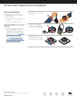
1. 

Load must be in line and 
centered when compensating 
linkages are not used

2. 

Support surfaces must be flat 
and inline

3. 

Support on the outer ring only

4. 

Load fixture must contact top 
inner ring 

Further mounting suggestions: 

Mounting and Installation

Below is information for proper mounting and 
installation .  Refer to the sensor spec sheet 
for thread information and proper load cell 
orientation to maximize performance and limit 
cable interference .

• 

Measurements are called out on the 
sensor spec sheet and have the following 
tolerances based on the number of 
decimal points present .

DECIMAL FORMAT

TOLERANCE

0.x

±0 .1"

0.xx

±0 .01"

0.xxx

±0 .005"

0.xxxx

±0 .001"

Active End

Fixed End

90°

Load Plate

Rod-end bearings 

& yokes/clevis

Alignment 

couplers

Summary of Contents for LCF Series

Page 1: ...Sensor Solutions Source Load Torque Pressure Multi Axis Calibration Instruments Software www futek com LCF Series Tension and Compression Sensor Family Manual...

Page 2: ...ments Software www futek com Table of Contents Features 3 Mechanical Installation 4 Maximum Installation Torque 5 Mounting and Installation 6 Bolt Torque and Tightening Pattern 7 Cable Care and Routin...

Page 3: ...ection of capacities ranging from 25 lb to 100 000 lb Internal amplifiers for voltage or current output available on select models Integrated TEDS calibration information available on some models Fati...

Page 4: ...be used to assist in determining if the sensor can withstand any unavoidable off axis loads and moments Extraneous load information can be found at http www futek com extraneous load factor An extran...

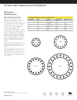
Page 5: ...IMUM BOLT TORQUE in lbs LCF300 25 100 0 50 100 100 0 250 500 100 0 LCF400 250 500 700 0 1000 700 0 2500 700 0 5000 700 0 LCF450 LCF455 300 700 0 500 140 0 1000 450 0 2000 1000 0 5000 2100 0 10000 2100...

Page 6: ...ring Further mounting suggestions Mounting and Installation Below is information for proper mounting and installation Refer to the sensor spec sheet for thread information and proper load cell orienta...

Page 7: ...g or heat treating is performed after grinding on the mounting plate re verify that the surface maintained its flatness Heating of materials can cause warpage Make sure that the mounting plate can sup...

Page 8: ...us of ten times the diameter of the sensor cable for dynamic or moving applications and not exceed a onetime static permanent bend of two to three times the diameter of the cable CABLE JACKET REFERENC...

Page 9: ...ctions Additional connection standard colors are Orange and Blue Consult the sensor s online spec sheet for any further wiring information LCF EXCITATION POWER LEVELS SENSOR FAMILY MAX EXCITATION LCF3...

Page 10: ...atstone bridge to generate a known fixed output from the sensor Shunt results can be used to set up instruments as well as compare changes to the load cell output over time and usage When selecting th...

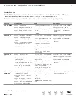
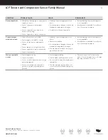
Page 11: ...oading surface Sensor loading surface is not obstruct ed or supported and able to flex under load Sensor support is not giving while sensor is loaded Internal disconnections or shorts would not be ava...

Page 12: ...le or noisy Sensor is exposed to temperature change Sensor support is not rigid and firm Sensor exposed to liquid or humidity Friction in assembly Stability of power supply and noise levels Fixtures f...

Page 13: ...and calibration period shall be defined based on application conditions endurance and usage Calibration data may be available online at http www futek com calibrationData aspx To send in your sensor o...

Reviews: