10 Thomas, Irvine, CA 92618
USA
T
(949)-465-090
F
(949)-465-0905
www.futek.com/support
IPM300 FAQ’s
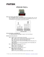
Where can I find the wiring guide for my display?
See “
Connections”
on page 1 of the Product Manual and the diagram below. Also, the
black and white wires from the power cord should be connected to pins 11 and 12. It is
not necessary to connect the green wire (ground) to the meter.
What do the buttons on the display do?
See “
Keyboard Operation and Setup”
on page 2 of the Product Manual.
What does each menu item do?
CAL
– allows the user to scale the meter for the sensor
dECP
– allows the user to choose desired position of the decimal point
U
Lo
– allows the user to input the low input signal (mV/V)
U
Hi
– allows the user to input the high input signal (mV/V)
rdLO
– allows the user to input the desired display value corresponding to the
low input signal
rdHi
– allows the user to input the desired display value corresponding to the
high input signal
Ky
1
– allows the user to choose a function for key 1
AL1
– sets key 1 as an alarm
PEAK
– sets key 1 as a peak switch
TArE
– sets key 1 as a tare switch
Ky
2
– allows the user to choose a function for key 2
AL2
– sets key 2 as an alarm
PEAK
– sets key 2 as a peak switch
TArE
– sets key 2 as a tare switch
GrnE
– sets key 2 as a switch between gross values and net values


