


IAC200 Quick Start Guide
Setup Finalization
Set Channel Select DIP switches ON for all Channels with a
connected sensor Output of IAC200 will now be one signal
of all connected sensors into one output with the same mV
output level that each sensor has been adjusted down to The
combined output will now reach the set mV output when all
sensors are fully loaded
If present, re-connect the ribbon cable from the center amplifier
to the IAC200 board on connection J6
Set the output of the IAC200 to S (mV/V) for non-amplified
IAC200, V (VDC) for voltage amplified IAC200 and I (mA) for
current amplified IAC200 FSH04735 is non-amplified S (mV/V),
FSH04736 is V (VDC), FSH04737 is I (mA) amplified current
version
Additional amplified setup:
•
The combined one mV output from all sensors will be the
input to the amplifier
•
To assist with amplifier setup instructions, convert the
adjusted one mV output of all connected sensors into mV/V
by dividing the mV output by the supply voltage used
during the setting of the one mV output This will be the
one mV/V combined signal going into the amplifier
•
Refer to the
of the IAA amplifier
for further instructions on how to set up the attached
amplifier
•
A Video of the IAA amplifier series is available on the
FUTEK website
•
IAA100 for Amplified IAC200 Voltage V(VDC) FSH04736
•
IAA200 for Amplified IAC200 Current I(mA) FSH04737
•
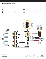
A
B
C
D
+E
–E
+S
–S
+E
–E
+S
–S
+E
–E
+S
–S
+E
–E
+S
–S
SENSOR INPUT
CH SELECT
J5
J6
0
4
3
2
1
8
7
6
5
4
3
2
1
1
CH 1
CH 2
AMPLIFIER
(OPTIONAL)
CH 3
CH 4
SIGNAL SELECT
CH1
0 = OFF
1 = ON
CH2
CH3
CH4
Shield
DIP Switch
Selection
Span
Span
CH SELECT
0
1
CH1
CH2
CH3
CH4
A
B
B
C
Shield
Shield
DIP SWITCH SELECTION:
SIGNAL SELECT
1
2
3
4
5
6
7
8
S (mV/V)
1
0
1
1
0
0
1
0
V (VDC)*
0
1
1
0
1
0
0
1
I (mA)*
0
1
1
0
0
1
0
1
* Use with amplifier option only
Sensor Solution Source
Load · Torque · Pressure · Multi-Axis · Calibration · Instruments · Software
www.futek.com