Futek IAC200 Quick Start Manual Download Page 6

Sensor Solution Source

Load · Torque · Pressure · Multi-Axis · Calibration · Instruments · Software

www.futek.com

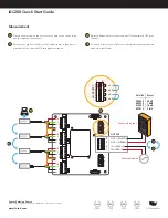
IAC200 Quick Start Guide

Measurement

Place a known load on the first sensor  Load does not have to be 
the full capacity of the sensor 

Record mV output on Voltmeter  Full capacity mV output level is 
a product of the sensor mV/V rating and excitation 

Adjust Channel Select for next channel ON and switch OFF prior 
channel 

Continue to process until all sensor individual outputs are known 
under the same load 

A

B

D

C

A

D

OUT – (WHITE)
OUT + (GREEN)
IN – (BLACK)
IN + (RED)

4
3
2
1

OUTPUT

+E

–E

+S

–S

+E

–E

+S

–S

+E

–E

+S

–S

+E

–E

+S

–S

Load

C

B

D

CH SELECT

0

1

CH1

CH2

CH3

CH4

Sensor mV output

Sensor excitation

Serial No.

755523

895325

616263

953512

Output

20mV

18mV

19mV

21mV

Summary of Contents for IAC200

Page 1: ...Sensor Solutions Source Load Torque Pressure Multi Axis Calibration Instruments Software www futek com IAC200 Four Channel Summing Junction Box Quick Start Guide...

Page 2: ...EM1006 A FUTEK reserves the right to modify its design and specifications without notice Please visit https www futek com TermsAndConditions for complete terms and conditions 10 Thomas Irvine CA 9261...

Page 3: ...e with certification Standard NIST and A2LA calibration requests are started online at https www futek com recalibrationterms Solutions are available at FUTEK to connect your IAC200 to the computer or...

Page 4: ...nt for amplified IAC200 disconnect the ribbon cable from the center amplifier to the IAC200 board on connection J6 Applies to FSH04736 Voltage output and FSH04737 Current output versions Enable one se...

Page 5: ...00 Refer to the sensor spec sheet online for the sensor s wiring Connect power supply to IAC200 for sensor excitation Refer to the sensor spec sheet online for max excitation Connect Voltage meter to...

Page 6: ...apacity mV output level is a product of the sensor mV V rating and excitation Adjust Channel Select for next channel ON and switch OFF prior channel Continue to process until all sensor individual out...

Page 7: ...inue process of Channel Select DIP Switches applied known load and adjustment of mV output down on each sensor until each sensor has the same mV output under the sample applied load To ensure best per...

Page 8: ...l connected sensors into mV V by dividing the mV output by the supply voltage used during the setting of the one mV output This will be the one mV V combined signal going into the amplifier Refer to t...

Reviews: