background image

42 

Gyro GS

www.laseto.be

       EN

Bedieningspaneel

9.  On/Off - Manually slope function

10.  Rotation speed

11.  Selection X / Y axis

12.  Slope function (digital)

13.  Up

14.  Down

15.  Scan function

16.  Tilt function

Receiver “Gyro Tracer GS” 

17.  On/Off

18.  Volume

19.  Receiver area

20.  LCD display

21.  Rod holder

22.  Bubble level

23.  Accuracy setup

Remote Control  “RM0505GS” 

24.  Ob/Off

25.  Turning speed

26.  Selection X / Y axis

27.  Slope function (digital)

28.  Up / Down

29.  Scan function

9

16

10

15

11

14

12

13

17

20

19

18

22

21

24

29

25

26

28

27

23

Summary of Contents for Gyro GS

Page 1: ...NL FR EN Gebruiksaanwijzing Mode d emploi Users Manual GYRO GS...

Page 2: ......

Page 3: ...GYRO GS 3 NL GYRO GS Gebruiksaanwijzing...

Page 4: ...4 Gyro GS www laseto be NL Inhoudsopgave 4 Algemene Beschrijving 5 Veiligheidsvoorschriften 12 Technische gegevens 19 Inhoudsopgave...

Page 5: ...sionele dubbele hellingslaser met rode lasertechnologie Ideaal voor het bepalen van hellingen Door middel van een krachtige laserstraal en een hoogwaardige ontvan ger is dit toestel aangewezen voor bu...

Page 6: ...unctie 16 Tilt Functie Laserontvanger Gyro Tracer GS 17 aan en uit schakelaar 18 volume geluidssignaal 19 ontvangstveld 20 LCD scherm 21 meetlathouder 22 waterpaslibel 23 fijninstelling Afstandsbedien...

Page 7: ...den De juistheid van uw werk valt volledig onder uw verantwoordelijkheid 9 Gebruik geen optische materialen om naar de laserstraal te kijken zoals een vergrootglas en let op voor spiegelende objecten...

Page 8: ...20u gebruikt worden Een volledige lading neemt ca 7u in beslag Horizontale uitlijning Het toestel dient op een stevige ondergrond geplaatst te worden Het is aangewezen om hiervoor een statief te gebru...

Page 9: ...keuze opzoeken Vanaf dat de ingestelde helling is bekomen zal het toestel automatisch terug gaan draaien De gekozen helling verschijnt in het display Wanneer dit proces onderbroken wordt door een slag...

Page 10: ...spectievelijk 120rpm 300rpm en 600rpm 600 rpm is de ideale snelheid voor het gebruik met ontvanger Loodpunt Het toestel beschikt over een loodpunt Dit loodpunt is zowel bovenaan als onderaan zichtbaar...

Page 11: ...Open het batterijvak en plaats de batterij zoals de polarisatie aangeeft Schakel de ontvanger aan d m v toets 17 de batterij indicator licht op in het LCD display links onderaan Rechtsboven in het LC...

Page 12: ...icatie of aanpassing van het instrument Gebruik na ontvreemding Gebruik van instrumenten met duidelijk zichtbare schade of defecten Gebruik van accessoires van andere fabrikanten zonder de nadrukkelij...

Page 13: ...ires Fabrikanten van niet Futech accessoires voor het instrument zijn verantwoordelijk voor het ontwikkelen invoeren en communiceren van veiligheidsconcepten voor hun producten en voor het functionere...

Page 14: ...ARSCHUWING Als het instrument wordt gebruikt met accessoires bv masten baken meetstokken kan het risico van blikseminslag worden vergroot Voorzorgsmaatregelen Gebruik het instrument niet tijdens onwee...

Page 15: ...ldaan Neem vooraf contact op met uw plaatselijke agent of vrachtvervoersbedrijf WAARSCHUWING Hoge mechanische belasting hoge omgevingstemperaturen of onderdompeling in vloeistoffen kan lekkage brand o...

Page 16: ...te allen tijde tegen het gebruik door onbevoegden LASERCLASSIFICATIE Algemeen De onderstaande richtlijnen in overeenstemming met de geldende internationale normen IEC 60825 1 2007 03 en IEC TR 60825...

Page 17: ...ht mogelijk bij wand nr 2 7 Stel de laser op hoogte in zodat het midden van het laserkruis op de markering van wand nr 2 staat 8 Draai het toestel vervolgens 180 en controleer het verschil tussen het...

Page 18: ...18 Gyro GS www laseto be NL...

Page 19: ...II 1 mW Nauwkeurigheid 1 mm 10 m Nivelleringsbereik 5 Hellingsbereik 10 Nivellering Motor Gebruiksduur 20 uur Power supply DC4 8 6V NI MH Dimensies 208 mm x 165 mm x 210mm Gewicht 2 800 kg Werkbereik...

Page 20: ......

Page 21: ...GYRO GS 21 FR GYRO GS Mode d emploi...

Page 22: ...22 Gyro GS www laseto be FR Sommaire 22 Description g n rale 23 Consignes de s curit 30 Donn es techniques 37 Inhoudsopgave...

Page 23: ...t ax s sur l utilit FUTECH GYRO GS Laser rotatif professionnel avec rayons laser vertes ultra visibles Nivellement automa tique au moyen du stabilisateurs lectroniques L amortissement lectronique perm...

Page 24: ...rs le bas 15 Fonction Scan 16 Fonction Tilt Laserontvanger Gyro Tracer GS 17 Marche Arr t 18 Volume 19 Zone de r ception 20 Ecran LCD 21 Porte canne 22 Niveau bulle 23 R glage fin T l commande RM0505G...

Page 25: ...se de votre travail tombe enti rement sous votre responsabilit 8 N utilisez aucun mat riel optique pour regarder le rayon laser comme par ex une loupe Veillez liminer tous les objets r fl chissants po...

Page 26: ...la batterie Alignement horizontal Installez l appareil sur une surface plate et solide L utilisation d un tr pied est recommand e Le laser peut tre fix sur le tr pied l aide de la vis 5 8 7 en bas de...

Page 27: ...choisie est affich e sur l cran Appuyez la touche X Y 11 encore une fois pour confirmer les pentes choisis Au cas ou l appareil a boug pendant cette proc dure l appareil vous l indiquera avec un bip...

Page 28: ...balayage du laser un angle la place d un cercle total pour retrouver le rayon plus facilement Ceci est surtout recommand en cas de haute luminosit ou de grandes distances Appuyez la touche scan 11 po...

Page 29: ...e Si vous avez opt pour un autre r cepteur consultez son mode d emploi qui vous a t fourni s par ment Enlevez les ventuels films de protection Ouvrez le compartiment batteries et placez la batterie en...

Page 30: ...ification ou transformation du produit Utilisation du produit apr s vol Utilisation de produits pr sentant des d fauts ou d g ts minemment reconnaissables Utilisation d accessoires d autres fabricants...

Page 31: ...es autres que la societ FUTECH Les fabricants d accessoires autres que la societ FUTECH utilis s avec le produit sont responsables de l laboration de la mise en pratique et de la diffusion de concepts...

Page 32: ...ansport AVERTISSEMENT En cas d utilisation de ce produit avec des accessoires par exemple des m ts mires et cannes il y a un risque de foudroiement Pr cautions Ne pas utiliser ce produit par temps d o...

Page 33: ...rer que les r glementations nationale et internationale en vigueur sont appliqu es Avant le transport ou l exp dition contacter la soci t charg e du transport AVERTISSEMENT Des contraintes m caniques...

Page 34: ...Seul le personnel autoris peut avoir acc s au produit Informations g n rales Les consignes suivantes conform ment aux normes internationales CEI 60825 1 2007 03 et CEI TR60825 14 2004 02 fournissent d...

Page 35: ...ser en hauteur au moyen du tr pied afin que Ie milieu du laser se trouve sur Ie marquage du mur n 2 8 Tournez ensuite I appareil de 180 et contr lez la diff rence entre Ie milieu de la croix laser et...

Page 36: ...ION si votre appareil n atteint pas la tol rance requise vous devez le renvoyer votre point service ou votre revendeur pour un entretien Les r parations effectu es par des personnes non autoris es ann...

Page 37: ...laser 1 mW Pr cision 1 mm 10 m Port e de nivellement 5 Port e de pente 10 Nivellement Motor Autonomie 20 h Alimntation DC4 8 6V NI MH Dimensions 208 mm x 165 mm x 210mm Poids 2 800 kg Port e de foncti...

Page 38: ......

Page 39: ...GYRO GS 39 EN GYRO GS Manual...

Page 40: ...40 Gyro GS www laseto be EN Table of contents 40 General description 41 Safety directions 48 Technical data 55 Inhoudsopgave...

Page 41: ...r innovative easy to use equipment FUTECH GYRO GS Professional Rotation laser with ultra visible laser beams Automatic levelling using electronic stabilizers This system enables greater stability and...

Page 42: ...Down 15 Scan function 16 Tilt function Receiver Gyro Tracer GS 17 On Off 18 Volume 19 Receiver area 20 LCD display 21 Rod holder 22 Bubble level 23 Accuracy setup Remote Control RM0505GS 24 Ob Off 25...

Page 43: ...ole responsibility for the accuracy of your work 8 Do not use any optical equipment such as a magnifying glass to view the laser beam and take care to remove all reflecting objects to avoid damage to...

Page 44: ...attery takes circa 7 hours Horizontal alignment Please install the device on a solid surface Usage of a tripod is recommended You can fix the laser device on the tripod with the 5 8 bold 7 on the bott...

Page 45: ...y The selected slope appears on the display Push the X Y selector 11 again to confirm the selected slopes In case the device has been moved or hit during this process the device will alert you with a...

Page 46: ...ad of a complete circle so you can find the beam more easily This is certainly recommended in places with high light intensity and or for long distances Switch on the scan function with the scan funct...

Page 47: ...nce If you have chosen another receiver use the manual that is delivered with it Remove foile protection from the device Open the battery place and place the battery as the polarisation indicates Turn...

Page 48: ...ain functions Modification or conversion of the product Use after misappropriation Use of products with obviously recognizable damages or defects Use with accessories from other manufacturers without...

Page 49: ...sories The manufacturers of non FUTECH accessories for the product are responsible for developing implementing and communicating safety concepts for their products and are also responsible for the eff...

Page 50: ...ts indicated in the user manual particularly after the product has been subjected to abnormal use and before and after important measurements WARNING If the product is used with accessories for exampl...

Page 51: ...ansportation or shipping contact your local pas senger or freight transport company WARNING High mechanical stress high ambient temperatures or immersion into fluids can cause leackage fire or explosi...

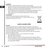
Page 52: ...tions in force in your country LASER CLASSIFICATION General The following directions in accordance with the state of the art international standard IEC 60825 1 2007 03 and IEC TR 60825 14 2004 02 prov...

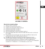
Page 53: ...that the middle of the laser cross is on the wall no 2 marker 8 Then turn the instrument through 180 and note the difference between the middle of the laser cross and the marker on wall no 1 9 This d...

Page 54: ...NB If your instrument does not reach the required tolerance it should be returned to your service centre or to your reseller for service Repairs carried out by unauthorised personnel will automatical...

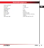
Page 55: ...er Class 1 mW Accuracy 1 mm 10 m Levelling range 5 Slope range 10 Levelling Motor Battery life 20 hours Power supply DC4 8 6V NI MH Dimensions 208 mm x 165 mm x 210mm Mass 2 800 kg Operating range 200...

Page 56: ...LASETO N V Ondernemersstraat 4 2500 Lier BELGIUM Tel 32 0 3 488 15 75 Fax 32 0 3 289 07 67 info laseto be www laseto be Uw dealer Votre revendeur Your Dealer Ihr H ndler...

Reviews: