2. INSTALLATION
2-24
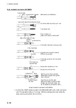
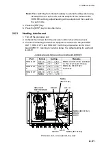
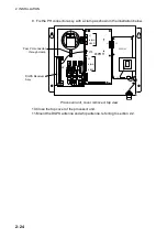
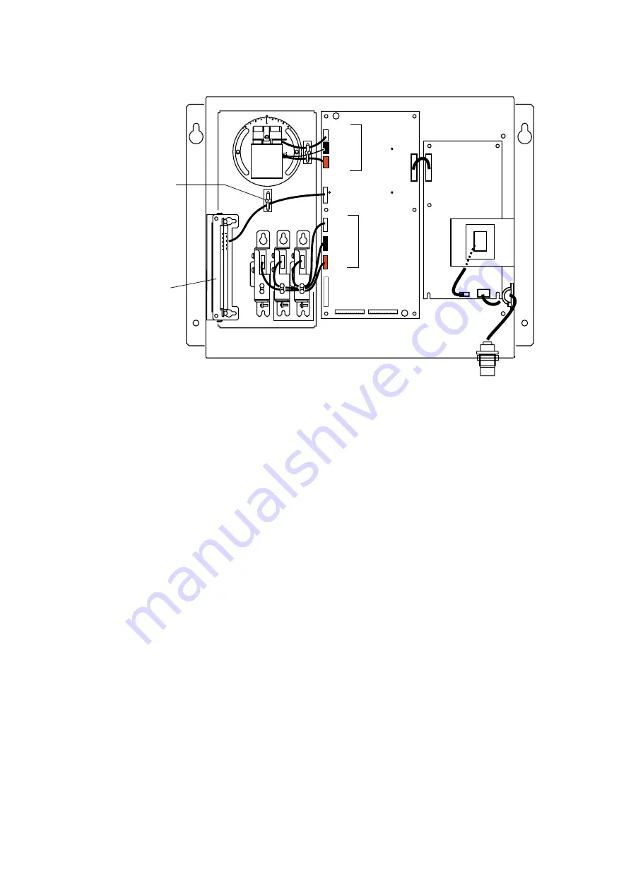
9. Fix the PH connector assy. with a clamp as shown in the illustration below.
J1
J4
J3
J1
J7
J10
9 (RED)
J8 (BLK)
J6
J2
J4 (RED)
J5 (BLK)
20P8164
20P8171
Pass PH connector
through clamp
DGPS Receiver
Assy.
Processor unit, cover removed, top view
10. Close the top cover of the processor unit.
11. Mount the DGPS antenna and whip antenna, referring to section 2.2.
Summary of Contents for SC-120
Page 1: ...SATELLITE COMPASS SC 120...
Page 10: ...This page is intentionally left blank...
Page 14: ...This page is intentionally left blank...
Page 58: ...This page is intentionally left blank...
Page 71: ...APPENDIX A 5 NAV OUT1 Port Output drive capability Max 10 mA HDG4 NAV2 port RS 232C level...
Page 82: ......
Page 83: ......
Page 84: ......
Page 87: ...Takahashi T Takahashi T D 1...
Page 88: ...Takahashi T Y Hatai D 2...
Page 89: ...Takahashi T Y Hatai D 3...
Page 90: ...Takahashi T Y Hatai D 4...
Page 91: ...Takahashi T Y Hatai D 5...
Page 92: ...D 6...
Page 93: ......
Page 94: ......
Page 96: ......

