2. INSTALLATION
2-14
2.3.4
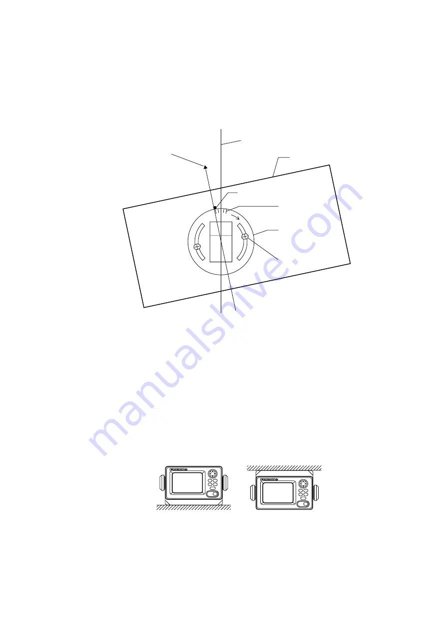
Adjusting for orientation error
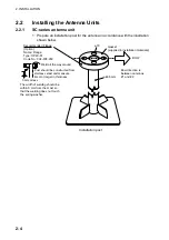
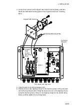
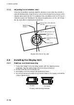
It may be impossible to perfectly align the processor unit on the fore-and-aft or
port-and-starboard line. Open the top cover, loosen the two fixing screws on the
angular rate sensor and turn. For example, if the orientation error is 2.5
°
to port,
rotate the sensor 2.5
°
starboard
.
The range of adjustment is -45
°
to +45
°.
Close
the top cover after completing the adjustment.
Reference
Direction
Processor Unit
Fore-aft line or Port-starboard
direction
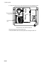
Bulkhead Mounting
Plate
Fixing Screw
Alignment hole on processor unit
Scale, every
2.5
°
Angular rate sensor, top view
2.4
Installing the Display Unit
2.4.1
Desktop, overhead mounting
1. Fasten the hanger to the mounting location with four tapping screws
(supplied). See the outline drawing for mounting dimensions.
2. Screw the knobs into the display unit.
3. Set display unit to the hanger and tighten the knobs.
4. Run the ground wire between the ground terminal on the display unit and the
ship’s superstructure.
Desktop
Overhead
Display unit mounting methods
Summary of Contents for SC-120
Page 1: ...SATELLITE COMPASS SC 120...
Page 10: ...This page is intentionally left blank...
Page 14: ...This page is intentionally left blank...
Page 58: ...This page is intentionally left blank...
Page 71: ...APPENDIX A 5 NAV OUT1 Port Output drive capability Max 10 mA HDG4 NAV2 port RS 232C level...
Page 82: ......
Page 83: ......
Page 84: ......
Page 87: ...Takahashi T Takahashi T D 1...
Page 88: ...Takahashi T Y Hatai D 2...
Page 89: ...Takahashi T Y Hatai D 3...
Page 90: ...Takahashi T Y Hatai D 4...
Page 91: ...Takahashi T Y Hatai D 5...
Page 92: ...D 6...
Page 93: ......
Page 94: ......
Page 96: ......


