background image


7

3 ADJUSTMENTS 

Adjust the MU-120C according to the equipment connected. Note that you can adjust the 
display currently selected, at the DISP selection window. (See section 4.3.) 
 

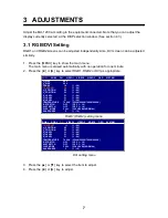
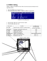
3.1 RGB/DVI Setting 

RGB1 and RGB2 screens can be adjusted independently. Also, DVI screen can be adjusted 
similarly. 
 
1.  Press the [MENU] key to show the main menu. 

The main menu is erased automatically with no operation for one minute. 

2.  Press the [

] or [

] key to select RGB1, RGB2 or DVI as appropriate. 


RGB1 (RGB2) setting menu 


DVI setting menu 

 
3.  Press the [

] or [

] key to select the item to adjust. 

4.  Press the [

] or [

] key to adjust. 

RGB1

      RGB2      DVI      VIDEO1      VIDEO2      VIDEO3      OSD      SYSTEM 

H_SIZE 640 
V_SIZE 480 
PHASE 

  16 

(1 – 32) 

CONTRAST 


44 

(1 – 64) 

H_POSITION 

  50   

(1 – 99) 

V_POSITION 

  25   

(1 – 40) 

R_LEVEL 

  31   

(1 – 64) 

G_LEVEL 

  31   

(1 – 64) 

B_LEVEL 

  31 

(1 – 64) 

TEMPERATURE 7000K 

(5500K/6500K/7000K/8000K) 

B STRETCH 

OFF 

(OFF, 1 – 10) 

W STRETCH 

OFF   

(OFF, 1 – 10)


DISP  MODE 

FULL   (FULL/EVEN/NORMAL) 

SHARPNESS 

  5  

(1 – 10) 

RGB1   RGB2   

DVI

   VIDEO1   VIDEO2   VIDEO3   OSD   SYSTEM 

CONTRAST                    44   

(1 – 64)

H_POSITION 

  25   

(1 – 50) 

V_POSITION 

  25   

(1 – 40) 

R_LEVEL 

  31   

(1 – 64) 

G_LEVEL 

  31   

(1 – 64) 

B_LEVEL 

  31   

(1 – 64) 

TEMPERATURE 7000K 

(5500K/6500K/7000K/8000K) 

B STRETCH 

OFF   

(OFF, 1 – 10) 

W STRETCH 

OFF   

(OFF, 1 – 10)


DISP MODE 

FULL    (FULL/EVEN/NORMAL) 

SHARPNESS 

  5  

(1 – 10) 

Summary of Contents for Mu 120c

Page 1: ...MULTI PURPOSE LCD DISPLAY MU 120C ...

Page 2: ......

Page 3: ...ng Label 1 Type 86 003 1011 1 Code No 100 236 231 WARNING Do not open the cover unless totally familiar with electrical circuits and service manual Improper handling can result in electrical shock Turn off the power at the switchboard before beginning the installation Fire or electrical shock can result if the power is left on Do not install the equipment where it may get wet from rain or water sp...

Page 4: ... 3 3 Menu Window Setting 10 3 4 Remote Controller Setting 12 4 OPERATION 13 4 1 Controls 13 4 2 Adjusting Display Brilliance 15 4 3 Choosing Source for Main Picture 16 4 4 Choosing Source for Picture in Picture 17 5 MAINTENANCE TROUBLESHOOTING 18 5 1 Maintenance 18 5 2 Troubleshooting 19 5 3 Clearing the Memory 20 SPECIFICATIONS SP 1 PACKING LISTS A 1 OUTLINE DRAWINGS D 1 INTERCONNECTION DIAGRAM S...

Page 5: ...achine can perform its intended function unless properly installed and maintained Please carefully read and follow the operation installation and maintenance procedures set forth in this manual We would appreciate feedback from you the end user about whether we are achieving our purposes Thank you for considering and purchasing FURUNO Features Main or remote display for radars video sounders sonar...

Page 6: ...log via IF8000 CSH 5L 8L XGA Analog FSV 24 24S 30 30S SXGA Analog FR 21X5 series SXGA Analog FAR 21X7 series SXGA DVI FEA 2107 SXGA DVI MODEL 1833C series VGA Analog MODEL 1833C BB series VGA Analog Not available for the portrait type Note The resolution of MU 120C is SVGA VGA XGA and SXGA signal may not be sharp in character or scan line The TFT LCD is constructed using the latest LCD techniques ...

Page 7: ...terials CP19 00100 000 012 630 1 set Power cable Accessories FP19 00601 001 403 200 1 set Option Name Type Code No Qty Remarks Hanger FP19 00700 001 403 240 1 w knob self tapping screws 000 146 500 1 Cable length 5 m 3COX 2P 6C 000 146 501 1 Cable length 10 m Cable Assy DVI D D SINGLELINK5M 000 149 054 1 Cable length 5 m Remote Controller RMC 200 000 012 629 1 See packing list at end of manual ...

Page 8: ...vi ...

Page 9: ... location keep in mind the following points Locate the unit out of direct sunlight Select a location where the display can be easily viewed and the controls can be easily operated Leave sufficient space around the unit for servicing and maintenance See the outline drawing for minimum servicing space The unit weighs 5 4 kg flush mounting 6 3 kg desktop mounting Be sure the mounting location is stro...

Page 10: ...make a cutout in the mounting location 3 Insert the display unit to the cutout and fasten the display unit to the mounting location with four self tapping screws 5x40 supplied as accessories Note Hex head bolts may also be used to fasten the display unit However their lengths should be such that they extend at least 10 mm beyond the bulkhead Waterproofing IP20 Waterproofing IPX5 Cosmetic cap Mount...

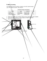
Page 11: ...it Name Type Code No Qty Hanger FP19 00701 001 403 250 1 Knob bolt FP03 09204 008 523 650 2 Self tapping screw 5x20 000 802 081 4 1 Fasten the hanger to the mounting location with four self tapping screws supplied 2 Screw knob bolts in hanger set unit to hanger and tighten knob bolts 3 Attach hard cover to protect the LCD Knob bolt Hanger Desktop mounting ...

Page 12: ...remote controller Attach the sticker to the remote controller at the location shown below Sticker VIDEO2 VIDEO1 BRILL RGB1 RGB2 MENU VIDEO3 DVI PIP1 PIP2 PIP3 RGB 1 RGB2 DVI VIDEO1 VIDEO2 VIDEO3 Remote controller RMC 200 WARNING Ensure battery polarity is correct Wrong polarity may cause the batteries to explode ...

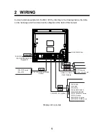
Page 13: ...C Ground terminal FCV 1200L CH 250 S CSH 5L 8L FSV 24 24S 30 30S GP GD 280 380 680 FR 1510 MARK 3 series FR 21X5 series MODEL1833C series MODEL1833C BB series DVI D FAR 21X7 series FEA 2107 12 24VDC RGB2 RGB1 VIDEO3 VIDEO1 VIDEO2 CCD camera Video recorder etc 3COX 2P 6C Option DVI D D SINGLELINK5M Option 2 5C2V or 3C2V Local supply MJ A3SPF0025 035C Supplied Display unit rear view ...

Page 14: ...R 21X5 series Model 1833C series Model 1833C BB series VIDEO1 VIDEO2 VIDEO3 Prepare the following cable locally Connector type RCA metal both ends Cable length shorter than 10 m 2 5C2V or 3C2V Japan Industrial Standard or the equivalent coaxial cable Impedance 75 Ω Conductor S 0 19 mm 0 5 mm 2 Vinyl Shield Cable 3C2V Insulator sheath Video cassette recorder CCD camera DVD player Grounding Fasten t...

Page 15: ...ting menu 3 Press the or key to select the item to adjust 4 Press the or key to adjust RGB1 RGB2 DVI VIDEO1 VIDEO2 VIDEO3 OSD SYSTEM H_SIZE 640 V_SIZE 480 PHASE 16 1 32 CONTRAST 44 1 64 H_POSITION 50 1 99 V_POSITION 25 1 40 R_LEVEL 31 1 64 G_LEVEL 31 1 64 B_LEVEL 31 1 64 TEMPERATURE 7000K 5500K 6500K 7000K 8000K B STRETCH OFF OFF 1 10 W STRETCH OFF OFF 1 10 DISP MODE FULL FULL EVEN NORMAL SHARPNES...

Page 16: ...500K 7000K 8000K B STRETCH Reduces noise on black color OFF 1 10 W STRETCH Emphasizes white color OFF 1 10 DISP MODE Selects the signal resolution FULL Shows the input signal on entire screen EVEN Shows the input signal with original size NORMAL Shows the input signal with same aspect ratio FULL EVEN NORMAL SHARPNESS Sharpens the edge horizontally 1 10 Warm color 5500K 6500K 7000K 8000K Cold color...

Page 17: ...25 mmx18mm 10 160 mmx129mm CONTRAST Increases or decrease contrast level 1 64 R_LEVEL Adjusts red color level 1 64 G_LEVEL Adjusts green color level 1 64 B_LEVEL Adjusts blue color level 1 64 TEMPERATURE Adjusts color temperature 5500K 6500K 7000K 8000K B STRETCH Reduces noise on black color OFF 1 10 W STRETCH Emphasizes white color OFF 1 10 Picture in picture window Picture in picture window RGB1...

Page 18: ...ss or to adjust Menu item Function Available range H_POSITION Moves the menu window horizontally 1 22 1 left 22 right V_POSITION Moves the menu window vertically 1 23 1 up 23 down TRANSLUCENT Translucentizes the menu window Off On CUSTOM NAME See the next section RGB1 RGB2 DVI VIDEO1 VIDEO2 VIDEO3 OSD SYSTEM H_POSITION 12 1 22 V_POSITION 23 1 23 TRANSLUCENT OFF OFF ON CUSTOM NAME RGB1 RGB1______ R...

Page 19: ...ect the character you want to change In the example below G is selected 5 Press the or key to select appropriate alphanumeric character In the example below 5 is selected 6 To change another signal name press and then press or to select it RGB1 RGB2 DVI VIDEO1 VIDEO2 VIDEO3 OSD SYSTEM H_POSITION 12 1 22 V_POSITION 23 1 23 TRANSLUCENT OFF OFF ON CUSTOM NAME RGB1 RGB1______ RGB2 RGB2______ DVI DVI__...

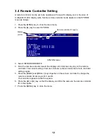
Page 20: ...ller The current setting of remote controller is shown inside the remote controller setting square 5 Press the RGB2 and BRILL keys together on the remote controller to change the remote controller ID among A B C and D Your selection appears inside the square 6 Press the or key so that the display unit ID is the same as the remote controller ID in the square 7 Press the MENU key to close the menu R...

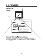
Page 21: ...hows the PIP selection window Power key Turns the power on off LED Optical sensor Display unit Power key Press the power key to turn the power on or off LED The LED changes color according to signal status as below Green The selected signal to be displayed is input correctly from the external device Orange The selected signal to be displayed is not input from the external device for five seconds ...

Page 22: ...the VIDEO1 signal in the picture in picture window PIP2 Shows the VIDEO2 in the picture in picture window PIP3 Shows the VIDEO3 in the picture in picture window BRILL Increases the display brilliance BRILL Decreases the display brilliance MENU Shows the main menu Arrow keys Selects the menu items When a picture in picture window is shown it remains on the RGB1 2 When the previous selection is PIP1...

Page 23: ...LL adjustment window BRILL window 3 Press the or key to adjust the brilliance Setting range 1 to 50 You can also adjust brilliance by pressing the BRILL key 4 Press the or key to close the window The window is erased when there is no operation within five seconds Note Avoid excessively low brilliance to prevent display irregularities BRILL 50 ...

Page 24: ...essing the DISP key continuously RGB1 2 The signal from the chosen RGB port is displayed on the entire screen DVI The signal from the DVI port is displayed on the entire screen VIDEO1 3 The external video from the appropriate VIDEO port is displayed on the entire screen 3 Press the or key to close the window The window is erased when there is no operation within five seconds Note The name of the s...

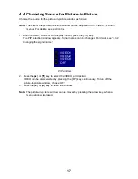
Page 25: ...press the PIP key The PIP selection window appears Signal names can be changed For detail see 3 3 2 Changing the signal name PIP window 2 Press the or key to select the VIDEO port desired VIDEO can be also selected by pressing the PIP key continuously To turn off the picture in picture window choose OFF 3 Press the or key to close the window Note The picture in picture window can be moved by press...

Page 26: ...LCD with a dry soft cloth Do not use chemical cleaners to clean any part of the display unit they can remove paint and markings Wipe the LCD carefully to prevent scratching using tissue paper and an LCD cleaner To remove dirt or salt deposits use an LCD cleaner wiping slowly with tissue paper so as to dissolve the dirt or salt Change paper frequently so the salt or dirt will not scratch the LCD Do...

Page 27: ... attempt to check inside the equipment there are no user serviceable parts inside Refer any work to a qualified technician Troubleshooting table Reason for no picture Remedy Ship s battery voltage too high Check battery voltage Fuse has blown Replace fuse Cable between MU 120C and external equipment has loosened Refasten cable Power cable has loosened Refasten cable You can confirm which signals a...

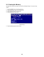
Page 28: ...TEM menu 3 Select DEFAULT RESET by arrow keys 4 Press the key to select YES SYSTEM menu 5 Press the key again to select reset RGB1 RGB2 DVI VIDEO1 VIDEO2 VIDEO3 OSD SYSTEM INFRARED REMOTE A A DEFAULT RESET YES All custom settings will be lost key cancel key reset INFORMATION RGB1 1280x1024 fH 80KHz fV 75Hz RGB2 640x480 fH 31KHz fV 60Hz DVI NO SIGNAL VIDEO1 NTSC VIDEO2 PAL VIDEO3 NO SIGNAL PROGRAM ...

Page 29: ...l RGB ports VESA VGA SVGA XGA SXGA 0 7 Vp p Synchronization TTL level DVI port VESA VGA SVGA XGA SXGA VIDEO ports NTSC PAL 2 POWER SUPPLY 2 1 Rated Voltage 12 24 VDC 4 0 2 0 A 3 ENVIRONMENTAL CONDITION 3 1 Ambient Temperature Display unit 15 C to 55 C Remote controller 5 C to 35 C 3 2 Relative Humidity 93 at 40 C 3 3 Waterproofing Display unit Front panel IPX5 Display unit Rear panel IP20 Remote c...

Page 30: ...品 SPARE PARTS 予備品 SPARE PARTS 1 SP19 00101 001 403 170 00 付属品 ACCESSORIES 付属品 ACCESSORIES 1 FP19 00601 001 403 200 00 工事材料 INSTALLATION MATERIALS ケーブル組品MJ CABLE ASSY 1 MJ A3SPF0025 035C 000 156 059 10 図書 DOCUMENT 取扱説明書 和 OPERATOR S MANUAL 1 OMJ 20290 000 149 089 0 型紙 TEMPLATE 1 C22 00304 000 149 091 0 1 コ ド番号末尾の は 選択品の代表型式 コードを表します CODE NUMBER ENDED BY INDICATES THE NUMBER OF TYPICAL MATERIAL 略...

Page 31: ......

Page 32: ... 番 号 NO 型名 規格 DESCRIPTIONS 1 1 3 ACCESSORIES 付属品表 19AR X 9501 パネルカバー 12 COSMETIC CAP 19 024 1014 0 4 100 314 990 1 CODE NO トラスタッピンネジ SELF TAPPING SCREW 5X40 SUS304 4 000 150 749 2 CODE NO 略図の寸法は 参考値です DIMENSIONS IN DRAWING FOR REFERENCE ONLY FURUNO ELECTRIC CO LTD 19AR X 9501 ...

Page 33: ......

Page 34: ......

Page 35: ...X 2P 6C 5m 10m φ8 5 ソナー レーダー プロッタ 魚群探知機 ECHO SOUNDER SONAR RADAR PLOTTER 2 3COX 2P 6C 5m 10m φ8 5 2 ソナー レーダー プロッタ 魚群探知機 ECHO SOUNDER SONAR RADAR PLOTTER DVI D D SINGLELINK5M 5m φ7 1 RADAR 2 RGB1 RGB2 DVI D VIDEO1 12 24VDC コンポジット映像信号用ケーブル COMPOSITE VIDEO SIGNAL CABLE 1 コンポジット映像信号用ケーブル COMPOSITE VIDEO SIGNAL CABLE 1 コンポジット映像信号用ケーブル COMPOSITE VIDEO SIGNAL CABLE 1 CCDカメラ CCD CAMERA ビデオデッキ VID...

Page 36: ...65 2111 0798 65 2111 Fax Fax 0798 65 4200 0798 65 4200 FIRST EDITION FIRST EDITION MAR MAR 2004 2004 Printed in Japan Printed in Japan All rights reserved All rights reserved A5 A5 APR APR 13 2006 13 2006 Pub No Pub No OME 20290 OME 20290 00014909000 00014909000 00014909000 00014909000 YOSH YOSH MU 120C MU 120C 0 0 0 1 4 9 0 9 0 0 0 0 0 0 1 4 9 0 9 0 0 0 OME20290A50 OME20290A50 OME20290A50 OME2029...

Reviews: