


12
12
Pub. No. OSE-44730-J
(1805, DAMI) FMD-3200/3200-BB/3300
Alert Icons and Their Meanings
TT/AIS Operations (con’t)
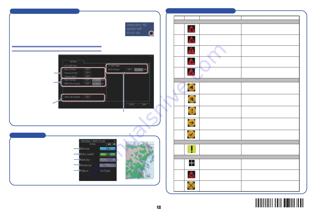
Open the chart menu, select TT/AIS Setting and then Setting. The below menus can also
be displayed by clicking the radio button on the pop-up menu
that appears when an item other than TT/AIS is selected on
the Overlay/NAV Tools box.
How to filter TT and AIS displays, sleep all targets
Emergency, Alarm alert
Warning alert
Caution alert
Other icons
Warning
Radar echo
Radar echo
Selects the antenna to feed the radar echo data.
Adjusts the picture gain.
Sets the degree of transparency for the overlay.
Activates, deactivates the radar overlay.
Status of the radar echo data, “OK” or “No Data”.
Radar Overlay
Set range (from own ship) to hide vessels
beyond the range set
Limit AIS display by AIS
category.
Sleeps all activated AIS
targets.
Filters AIS targets by
range, speed.
1
2
3
4
5
6
7
8
9
11
13
12
14
10
Active - unacknowledged
alarm
Flashing red triangle. Loudspeaker
symbol at center.
Presented together with alert text.
Flashing red triangle. Tick mark at center.
Presented together with alert text.
Flashing red triangle. Loudspeaker symbol at
center with diagonal line through symbol.
Presented together with alert text.
Steadily displayed red triangle.
Excalamtion mark at center.
Presented together with alert text.
Steadily displayed red triangle.
Right arrow at center.
Presented together with alert text.
Flashing yellow-orange circle.
Loudspeaker symbol at center.
Presented together with alert text.
Flashing yellow-orange circle. Tick mark at
center.
Presented together with alert text.
Steadily displayed yellow square.
Excalamtion mark at center.
Presented together with alert text.
Red triangle. Cross in center of circle.
Presented together with icon numbers 1,
2 and 5.
Yellow-orange circle. Cross in center of
circle. Presented together with icon
numbers 6, 7 and 10.
Plus sign. Presented together with icon
numbers 1 to 11.
Flashing yellow-orange circle. Loudspeaker
symbol at center with diagonal line through
symbol. Presented together with alert text.
Steadily displayed yellow-orange
circle. Excalamtion mark at center.
Presented together with alert text.
Steadily displayed yellow-orange
circle. Right arrow at center.
Presented together with alert text.
Active - silenced alarm
Active - acknowledged alarm
Active - reponsibility
tranferred alarm
Rectified - unacknowledged
alarm
Active - unacknowledged
warning
Active - silenced warning
Caution
Aggregation
Active - acknowledged
warning
Active - reponsibility
tranferred warning
Rectified - unacknowledged
warning
Acknowledged not allowed
for alarm
No.
Icon
Alert state
Description
䢲䢲䢲䢳䢹䢸䢳䢴䢹䢳䢺


