4. INSTALLATION
44
around the cable where it passes through
the transom.
8. Position the two cable clamps and fasten
them in place. If used, push the cable cov-
er over the cable and screw it in place.
9. Route the cable to the instrument being
careful not to tear the cable jacket when
passing it though the bulkhead(s) and
other parts of the boat. To reduce electri-
cal interference, separate the sensor ca-
ble from other electrical wiring and "noise"
sources. Coil any excess cable and se-
cure it in place with zip-ties to prevent
damage.
4.7
Speed/Tempera-
ture Sensor
(option)
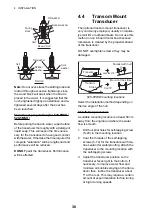
The speed/temperature sensors (ST-02MSB
and ST-02PSB) are designed for thru-hull
mounting. Install them as shown below.
Mounting considerations
Select a suitable mounting location, consider-
ing the following:
• Select a mid-boat flat position. The sensor
does not have to be installed perfectly per-
pendicular.
• Select a location where the transducer will
not be damaged in trailering, launching,
hauling, and storage.
• Select a location in the forward direction
viewing from the drain hole, to allow for cir-
culation of cooling water.
• Select a location away from water flow from
keel, water discharge pipe, etc.
• Vibration at the location shall be minimal.
• Do not install fore of the transducer of a fish
finder, to prevent disturbance (and loss of
performance) to the fish finder.
1. Dry-dock the boat.
2. Make a hole of approx. 51 mm diameter in
the mounting location.
3. Unfasten the locknut and remove the sen-
sor section.
4. Apply marine sealant to the flange of the
sensor. The height of the coat should be
approx. 6 mm
5. Pass the sensor casing through the hole.
6. Face the notch on the sensor toward
boat's bow and tighten the flange.
7. Set the sensor section to the sensor cas-
ing and tighten the locknut.
8. Launch the boat and check for water leak-
age around the sensor.
Speed/Temperature sensor
ST-02MSB, ST-02PSB
4.8
Wiring
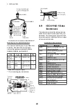
Connect the cable assy. (supplied) to the [12-
24 VDC/NMEA] port, and the transducer ca-
ble to the [XDR] port. Refer to the intercon-
nection diagram to connect cables. Leave
slack in cables to facilitate checking and
maintenance. See the next page for how to
ground the display unit.
Locknut
123
Face
"notch"
toward
bow.
Flange
nut
51
Brim
ø77
Coat with
marine
sealant.
Unit: mm
Transducer
cable
Ground
Switchboard, ground terminal,
external equipment
Cable assy.
(KON-004-02M, 2 m)
Transducer
Example:
FCV-628
(option)
Summary of Contents for FCV-588
Page 1: ...B R I L L GAIN...
Page 72: ...D 1 13 Jan 2012 Y NISHIYAMA...
Page 73: ...D 2 13 Jan 2012 Y NISHIYAMA...
Page 74: ...D 3 13 Jan 2012 Y NISHIYAMA...
Page 75: ...D 4 13 Jan 2012 Y NISHIYAMA...
Page 76: ...D...


