4. INSTALLATION
36
Desktop mount
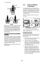
1. Remove the tape
from the bottom
of the bracket
assembly.
2. Fix the bracket
assembly to a desktop with four self-tap-
ping screws (5
25, supplied).
Be sure to follow the recommended main-
tenance space show in the outline draw-
ing. Insufficient space may cause
damage to connectors when disconnect-
ing and reconnecting them.
3. Loosely screw knob into the bracket as-
sembly.
4. Set the display unit to the bracket assem-
bly.
5. Adjust the angle of the display unit and
then tighten the knob to fix the display
unit.
Note:
When loosening the knob to adjust
the angle of the display, do not tilt the unit
90-degree backward or forward. The ca-
ble connector may be damaged if it con-
tacts the bracket.
6. Attach the hard cover to the display unit
for protection when the unit is not in use.
Flush mount (in a console)
Select a flat mounting location and install the
unit as shown below.
It is recommended to set up a dedicated
breaker when flush mounting the unit, since it
will be difficult to disconnect cables.
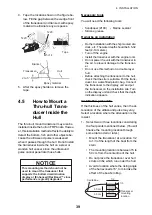
1. Using the paper template (supplied),
make a cutout in the mounting location.
2. Unfasten four washer head screws on the
rear of the display unit to remove the
bracket cover and the cover sponge
(FCV-588 only).
3. Set the flush mounting sponge (supplied)
to the display unit.
4. Screw four threaded rods (supplied) to
the display unit.
5. Set the display unit to the cutout.
6. Fasten the display unit from behind with
four sets of flat washers, spring washers
and wing nuts (supplied).
4.3
Thru-hull Mount
Transducer
520-PLD
For details of the installation, see the manual
of the transducer.
Transducer mounting location (for 520-
5PSD/520-5MSD)
The thru-hull mount transducer provides the
best performance of all, since the transducer
protrudes from the hull and the effect of air
bubbles and turbulence near the hull skin is
reduced. When the boat has a keel, the trans-
ducer should be at least 30 cm away from it.
The performance of this fish finder is directly
related to the mounting location of the trans-
ducer, especially for high-speed cruising. The
installation should be planned in advance,
keeping the length of the transducer cable
and the following factors in mind:
• Air bubbles and turbulence caused by
movement of the boat seriously degrade
the sounding capability of the transducer.
The transducer should, therefore, be locat-
ed in a position where water flow is the
Tape
(FCV-628 only)
FCV-628
FCV-588
Washer head screw
Bracket cover
Cover
sponge
Summary of Contents for FCV-588
Page 1: ...B R I L L GAIN...
Page 72: ...D 1 13 Jan 2012 Y NISHIYAMA...
Page 73: ...D 2 13 Jan 2012 Y NISHIYAMA...
Page 74: ...D 3 13 Jan 2012 Y NISHIYAMA...
Page 75: ...D 4 13 Jan 2012 Y NISHIYAMA...
Page 76: ...D...


