


1. OPERATIONAL OVERVIEW
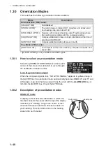
1-58
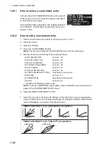
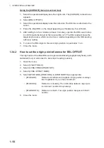
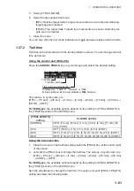
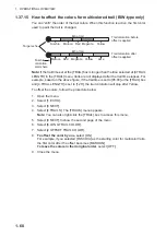
How to measure range and bearing from the control unit (RCU-014)
Range and bearing can be measure using the
EBL OFFSET
key.
1. Press the
EBL ON
key to activate EBL1.
2. Place the cursor inside the operational display area, then press the
EBL OFFSET
key. EBL1 moves to the cursor.
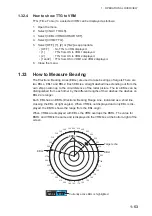
3. Place the cursor (EBL1 moves with the cursor) on a target of interest. (Shown as
“Target 1” in the above example), then press the
EBL OFFSET
key.
4. Rotate the
EBL
knob to move the EBL until it passes through another target of in-
terest. (Shown as “Target 2” in the above example).
5. Place the cursor on the [VRM1] box.
6. Rotate the
VRM
knob until the range marker on the EBL is on the inside edge of
Target 2. The readouts for EBL1 and VRM1, at the bottom of the screen, indicate
the bearing and range between the Target 1 and Target 2.
7. You can repeat the same procedure on third and fourth targets (shown as “Target
3” and “Target 4” in the above example) by using the No. 2 EBL and the No. 2
VRM.
Bearing is shown relative to own ship with suffix "R" or as a true bearing with suffix "T"
depending on EBL relative/true settings in the [EBL•VRM] menu.
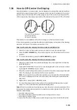
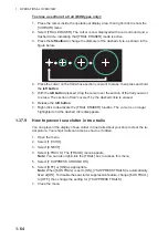
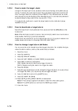
How to reset the EBL origin to the center of the screen
1. Place the cursor on the box for the EBL to reset, then left-click. The selected EBL
is now active and highlighted.
2. Place the cursor inside the operational display area, then right-click. The [CUR-
SOR] context menu appears.
3. Select [EBL OFFSET]. The cursor is now displayed with a red surround.
4. Left-click to return the EBL to the center of the display.
5. Right-click to deactivate the [EBL OFFSET] mode. The red surround on the cursor
disappears.
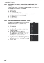
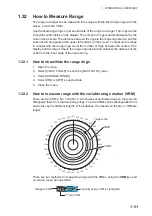
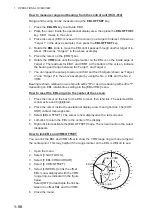
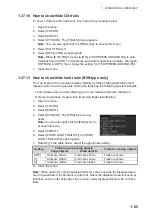
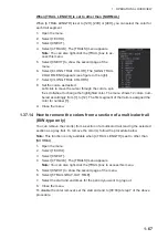
How to link EBL and VRM OFFSET
You can link the EBL and VRM offset to show the VRM range ring with one target as
the center-point. This may helpful if the range marker on the EBL is difficult to see.
1. Open the menu.
2. Select [3 NAV TOOLS].
3. Select [3 EBL•VRM•CURSOR].
4. Select [8 VRM OFFSET].
5. Select [LINK EBL] to link the offset
EBL is now displayed with the VRM
range ring, as indicated in the figure
below.
Select [OFF] to deactivate the link be-
tween the offset EBL and the VRM.
6. Close the menu.
000
010
020
030
040
050
060
070
080
090
100
110
120
130
140
150
160
170
180
190
200
210
220
230
240
250
260
270
280
290
300
310
320
330
340
350
Target 2
Target 2
EBL1
EBL1
EBL origin
EBL origin
Linked VRM1
Linked VRM1
Target 1
Target 1
Summary of Contents for FAR-2218
Page 132: ...1 OPERATIONAL OVERVIEW 1 110 This page is intentionally left blank ...
Page 176: ...3 TARGET TRACKING TT 3 36 This page is intentionally left blank ...
Page 202: ...4 AIS OPERATION 4 26 This page is intentionally left blank ...
Page 232: ...5 VIDEO PLOTTER OPERATION 5 30 This page is intentionally left blank ...
Page 294: ......