background image

14

• Straight edge
• Marine sealant
• Pencil
• Zip-ties
• Water-based antifouling paint (mandatory in salt water).

Mounting location

To ensure the best performance, the sensor must be submerged in aeration-free and 
turbulence-free water. Mount the sensor close to the centerline of the boat. On slower 
heavier displacement hulls, positioning it farther from the centerline is acceptable.

Allow adequate space above the bracket for it to release and rotate the sensor up-
ward.

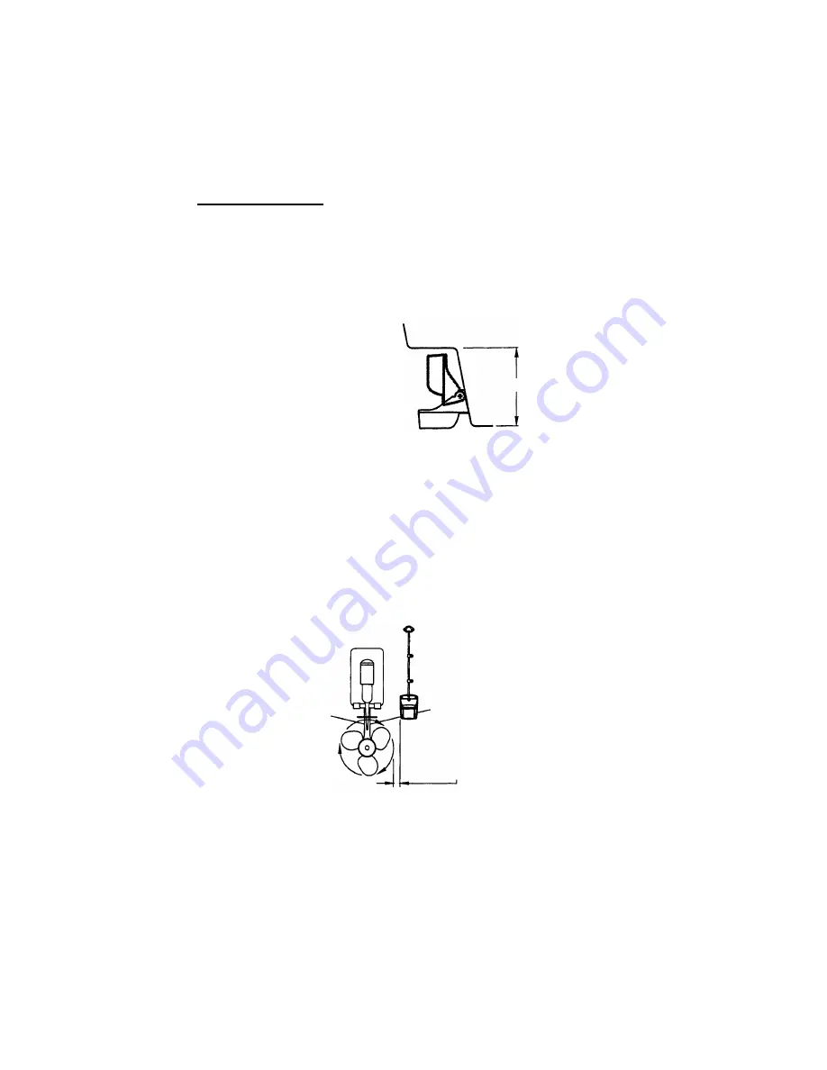
Height required at mounting location

Note 1:

 Do not mount the sensor in an area of turbulence or bubbles: near water in-

take or discharge openings; behind strakes, struts, fittings, or hull irregularities; behind 
eroding paint (an indication of turbulence).

Note 2:

 Avoid mounting the sensor where the boat may be supported during trailering, 

launching, hauling, and storage.

Note 3: For single drive boat,

 mount on the starboard side at least 75 mm (3") be-

yond the swing radius of the propeller.

Mounting location on single drive boat

Note 4: For twin drive boat,

 mount between the drives.

Height

Height without
speed sensor
191mm (7-1/2")

Height with
speed sensor
213mm (8-1/2")

75 mm (3")
minimum beyond
swing radius

Summary of Contents for DFF1

Page 1: ...NETWORK SOUNDER DFF1 OPERATOR S MANUAL www furuno com MODEL ...

Page 2: ......

Page 3: ...is product according to local regulations for the disposal of industrial waste For disposal in the USA see the homepage of the Electronics Industries Alliance http www eiae org for the correct method of disposal How to discard a used battery Some FURUNO products have a battery ies To see if your product has a battery see the chapter on Maintenance Follow the instructions below if a battery is used...

Page 4: ...ment WARNING WARNING Do not open the equipment Only qualified personnel should work inside the equipment Do not disassemble or modify the equipment Fire electrical shock or serious injury can result Turn off the equipment immediately if it is emitting smoke or fire Fire or electrical shock can result if the power is left on Turn off the power immediately if water leaks into the equipment or an obj...

Page 5: ...magnetic compass WARNING WARNING Do not open the equipment Only qualified personnel should work inside the equipment Turn off the power before beginning the installation Fire or electrical shock can result if the power is left on Confirm that is no water leakage at the transducer and temperature sensor Water leakage can sink the vessel Also confirm that neither the transducer or sensor will loosen...

Page 6: ...8 1 5 4 Installation procedure 9 1 6 Optional Water Temperature Sensor ST 02MSB ST 02PSB 10 1 7 Optional Temperature Sensors 11 1 7 1 Transom mount temperature sensor T 02MTB 11 1 7 2 Thru hull temperature sensor T 02MSB T 03MSB 12 1 8 Optionial Triducers 13 1 8 1 Thru hull triducer 525STID MSD 13 1 8 2 Transom mount triducer 525STID PWD 13 2 WIRING 19 2 1 Optional Temperature Speed Sensor Tempera...

Page 7: ...ransducer 520 5PSD 525 5PWD 520 5MSD Triducer 525STID MSD 525STID PWD Rectifier PR 62 100 110 220 230 VAC 1f 50 60 Hz Standard supply Optional supply External equipment Speed temperature sensor ST 02MSB ST 02PSB Temperature sensor T 02MTB T 02MSB T 03MSB Radar Plotter Radar Plotter Radar Plotter HUB HUB may be connected to 3 sets of NavNet radar or plotter NavNet series NavNet series 1 kW Transduc...

Page 8: ...0 000 167 177 10 10 m HUB 101 Inner Hull Kit S 22S0191 2 000 802 598 Triducer 525STID MSD 000 011 783 Thru hull mount metallic 525STID PWD 000 011 784 Transom mount plastic Transducer 520 5PSD 000 015 204 Thru hull mount plastic 520 5PWD 000 015 126 Transom mount plastic 520 5MSD 000 015 212 Thru hull mount metallic 50B 6 000 015 042 10 m 1 kW 50B 6B 000 015 043 15 m 1 kW 50B 9B 000 015 065 15 m 1...

Page 9: ...nerating equipment such as motors and generators Leave slack in cables for maintenance and servicing ease A magnetic compass will be affected if the network sounder is placed too close to it Observe the compass safe distances noted in the safety instructions to prevent dis turbance to the magnetic compass Fasten the network sounder to the mounting location with four self tapping screws 4 20 NOTE T...

Page 10: ...therefore be located in a position where water flow is the smoothest Noise from the propellers also adversely affects performance and the transducer should not be mounted nearby The lifting strakes are notorious for creating acoustic noise and these must be avoided by keeping the transducer inboard of them The transducer must always remain submerged even when the boat is rolling pitching or up on ...

Page 11: ...g location on deep V hull High speed V planing hull Transducer mounting location on high speed V planing hull Position 1 2 to 1 3 length of the hull from stern 15 30 cm from center line inside first lifting strakes Within the wetted bottom area Deadrise angle within 15 ...

Page 12: ...ugh to pass the threaded stuffing tube of the transducer through the hull making sure it is drilled vertically 3 Apply a sufficient amount of high quality caulking compound to the top surface of the transducer around the threads of the stuffing tube and inside the mounting hole and fairing blocks if used to ensure watertight mounting 4 Mount the transducer and fairing blocks and tighten the lockin...

Page 13: ...m the engine and where the water flow is smooth 1 Drill four pilot holes in the mounting location 2 Attach the transducer to the bracket with self tapping screws supplied 3 Adjust the transducer position so the transducer faces right to the seabed Note If necessary to improve water flow and minimize air bubbles staying on the transducer face incline the transducer about 5 at the rear This may requ...

Page 14: ...he boat is hauled out of the water and put on the trailer Transom mount transducer projecting from hull 1 4 3 Transducer preparation Before putting the boat in water wipe the face of the transducer thoroughly with a de tergent liquid soap This will lessen the time necessary for the transducer to have good contact with the water Otherwise the time required for complete saturation will be lengthened...

Page 15: ... location The mounting location should be where the hull is of single hull thickness and is void of air or flotation materials other than solid fiberglass between the transducer face and the water Do not place the transducer over hull struts or ribs which run under the hull Avoid a location where the rising angle of the hull exceeds 15 to minimize the effect of the boat s rolling You will finalize...

Page 16: ...Attaching transducer to hull with silicone sealant 4 Connect this unit to NavNet equipment and turn on the NavNet equipment 5 Set up the NavNet equipment to show single frequency display 6 Set the gain to 50 7 Set the range to 10 Case 1 The installation is proper if the bottom echo is displayed in red and the depth indi cation is shown Go to step 9 Case 2 The bottom echo is not displayed in red wh...

Page 17: ... of cooling water Select a place free from vibration Procedure 1 Dry dock the boat 2 Make a hole of approx 51 mm in diameter in the mounting location 3 Unfasten locknut and remove the sensor section 4 Apply high grade sealant to the flange of the sensor 5 Pass the sensor casing through the hole 6 Face the notch on the sensor toward boat s bow and tighten the flange 7 Set the sensor section to the ...

Page 18: ...e at a convenient location with cable clamp When the cable is led in through the transom board make a hole of approx 17 mm in diameter to pass the connector After passing the cable fill the hole with a seal ing compound Temperature sensor T 02MTB M5x20 Mount sensor flush with hull bottom D D 50cm ...

Page 19: ...location should not be such that the transducer may be damaged when the boat is dry docked Locate away from equipment which gives off heat Locate away from drain pipes Select a location where vibration is minimal Assembling temperature sensor T 02MSB T 03MSB Sensor Cable Locknut Washer Rubber Gasket φ21 mm Apply sealant T 02MSB Locknut Locknut Washer Rubber Gasket Apply sealant Thicker than 25 mm ...

Page 20: ...l Check for a speed reading and the approximate air temperature If there is no reading return the sensor to your place of purchase Tools and materials needed Scissors Masking tap Safety goggles Dust mask Electric drill Drill bit for Bracket holes 4mm 23 or 9 64 Fiberglass hull chamfer bit preferred 6mm or 1 4 Transom hole 19mm or 3 4 optional Cable clamp holes 3mm or 1 8 Screwdrivers 133 mm 27 mm ...

Page 21: ...d at mounting location Note 1 Do not mount the sensor in an area of turbulence or bubbles near water in take or discharge openings behind strakes struts fittings or hull irregularities behind eroding paint an indication of turbulence Note 2 Avoid mounting the sensor where the boat may be supported during trailering launching hauling and storage Note 3 For single drive boat mount on the starboard s...

Page 22: ...at If a cham fer bit or countersink bit is not available start drilling with a 6mm or 1 4 bit to a depth of 1 mm 1 16 4 If you know your transom angle the bracket is designed for a standard 13 tran som angle 11 18 angle No shim is required Skip to step 3 in Adjusting Other angles The shim is required Skip to step 2 of Adjusting If you do not know the transom angle temporarily attach the bracket an...

Page 23: ...is underway Adjusting 1 Using a straight edge sight the underside of the sensor relative to the underside of the hull The stern of the sensor should be 1 3 mm 1 16 1 8 below the bow of the sensor or parallel to the bottom of the hull Note Do not position the bow of the sensor lower than the stern because aeration will occur 2 To adjust the sensor s angle relative to the hull use the tapered plasti...

Page 24: ...hat the angle of the sensor is correct Note Do not position the sensor farther into the water than necessary to avoid increasing drag spray and water noise and reducing boat speed 5 Using the vertical adjustment space on the bracket slots slide the sensor up or down to provide a projection of 3 mm 1 8 Tighten the screws Vertical adjustment and cable routing 11 transom angle NO SHIM 12 18 transom a...

Page 25: ... a hole has been drilled in the transom open the appropriate slot in the transom cable cover Position the cover over the cable where it enters the hull Mark the two mounting holes 6 At each of the marked locations use a 3 mm or 1 8 bit to drill a hole 10 mm 3 8 deep The prevent drilling too deeply wrap masking tape around the bit 10 mm 3 8 from the point 7 Apply marine sealant to the threads of th...

Page 26: ...e Use a closed type lug to make the ground connection at the network sounder Do not use an open type lug External KP Consult with your dealer if connection of an external KP is required to reduce interfer ence from another transducer TRANSDUCER BATTERY GROUND White Black Shield green NETWORK MODE SW 1 2 3 4 XDR 12 24 VDC 1 1 0 4 A 1 GROUND WIRE IV 1 25sq 12 24 VDC DFF1 3 GND 2 MOD Z072 050 5 m opt...

Page 27: ... TEMP TEMP0V SPD0V SPD V NC 1 2 3 4 5 6 MJ A10SRMD NC NC NC NC NC NC NC XDR XDR SHIELD XDR 1 2 3 4 5 6 7 8 9 10 4 7 3 1 2 5 6 8 9 10 MJ A10SPF TEMP TEMP0V SPD0V SHIELD SPD V NC NC XDR XDR SHIELD XDR XDR port on the DFF1 Temperature sensor OR Temperature speed sensor Transducer Tape connector with self vulcanizing tape and then vinyl tape to waterproof connector Bind tape end with cable tie MJ A6SR...

Page 28: ...atching Box MB 1100 000 041 000 1 Cable w 8P connector sup plied for connection to net work sounder Crimp on Lug FV1 25 3 Red 000 538 113 6 Cord Lock NC 1 000 516 650 1 For use with separate trans ducer TO NETWORK SOUNDER Cable is fitted with 8P connector 8P 10P converter connector is required Shield 50B 6 6B 50B 9B 200B 5S 50kHz 200kHz SHIELD BLK RED BLK RED TB2 1 2 3 4 5 J2 J1 BLK 3 2 1 WHT TB1 ...

Page 29: ...sen three screws fixing the inside cover and slide cover forward to detach it 4 Set the 1 segment of DIP SW S2 according to transducer connected PCB 02P6353 5 Close the inside and outside covers and connect the power cable For NavNet 3D TZtouch Set the transducer type at the NavNet 3D TZtouch See re spective installation manual for the procedure WARNING Do not open the equipment unless totally fam...

Page 30: ...vNet OFF Sounder powered on off by NavNet ON Sounder not powered on off by NavNet 2 Default OFF IP number Currently no use OFF IP0 ON IP1 3 Default OFF Factory testing OFF Testing OFF ON Testing ON 4 Default ON Automatic IP setting Currently no use OFF Automatic IP enabled ON Automatic IP disabled NETWORK MODE SW 1 2 3 4 XDR 12 24 VDC 1 1 0 4 A 1 3 GND ON 1 2 3 4 2 ON 1 2 3 4 OFF NavNet 3D MODE sw...

Page 31: ...s described in the table below The LED lights for approximately 20 seconds after turning on the power while the equipment is being initialized DFF1 top view LED state Meaning Lighting continuously NavNet is not showing the sounder display or sounder is not connected to NavNet Flashing every two seconds Normal operation Flashing every four seconds Factory test mode LED ...

Page 32: ...necessary Power supply voltage Check voltage If out of rating correct problem Cleaning the network sounder s cabinet Dust or dirt on the cabinet may be removed with a dry cloth Do not use chemical based cleaners to clean the cabinet they can remove paint and markings Transducer Marine life on the transducer face will result in a gradual decrease in sensitivity Check the transducer face for cleanli...

Page 33: ...from equipment fault and reverse polarity of the ship s mains If the equipment cannot be powered a fuse may have blown Find out the cause for blown fuse before replacing a fuse If a fuse blows again after replacement contact a FURUNO agent or dealer for advice WARNING Use the proper fuse Use of a wrong fuse can result in damage to the equipment or cause fire ...

Page 34: ...h Range and Pulse Repetition Rate 2 POWER SUPPLY 12 24 VDC 1 1 0 4 A at 1 kW output 3 ENVIRONMENTAL CONDITION 3 1 Ambient Temperature 15 C to 55 C 3 2 Relative Humidity 93 at 40 C 3 3 Dustproofing waterproofing IP20 not waterproof IEC60529 3 4 Vibration IEC 60945 Ed4 2 5 Hz and up to 13 2 Hz with an excursion of 1 mm 10 7 m s2 maximum acceleration at 13 2 Hz 13 2 100 Hz with a constant maximum acc...

Page 35: ...J POWER CABLE ASSY MJ A3SPF0028 035C 000 164 952 10 1 トラスタッピンネジ 1シュ SELF TAPPING SCREW 4X20 SUS304 000 158 850 10 4 図書 DOCUMENT 取扱説明書 OPERATOR S MANUAL OM 20360 000 170 908 1 1 コ ド番号末尾の は 選択品の代表コードを表します CODE NUMBER ENDING WITH INDICATES THE CODE NUMBER OF REPRESENTATIVE MATERIAL 略図の寸法は 参考値です DIMENSIONS IN DRAWING FOR REFERENCE ONLY 型式 コード番号が2段の場合 下段より上段に代わる過渡期品であり どちらかが入っています なお 品質は変わりません TWO...

Page 36: ......

Page 37: ......

Page 38: ...1 10 9 8 7 6 5 4 2 3 NC XDR SHIELD 12V 02S4147 XDR 10 9 8 1 6 5 4 3 2 MJ A6SRMD 1 1 6 5 4 3 2 MJ A10SRMD 2 J4 J4 SPD_XDR SPD TD_ID_0V TEMP_XDR TD_ID_XDR TEMP_0V XDR_P XDR_M MJ A10SPF 3 3 3 3 2 520ST PWD 524ST MSD 525STID MSD 525STID PWD MJ A10SPF MJ A6SPF MJ A6SPF TRANSDUCER 送受波器 水温 船速センサー TEMP SPEED SENSOR ST 02MSB ST 02PSB 2 OR T 02MTB T 03MSB T 02MSB または 2 TEMP SENSOR 温度センサー 520 5PWD 520 5MSD 5...

Page 39: ...icient Otherwise the invoice with serial number name and stamp of the dealer and date of purchase is shown For the Onboard Warranty your FURUNO certified dealer will take care of all registrations 5 Warranty Claims For the Standard Warranty simply send the defective product together with the invoice to a FURUNO national distributor For the Onboard Warranty contact a FURUNO national distributor or ...

Page 40: ...c or its authorized dealer at the time of request for warranty service This warranty is valid for installation of products manufactured by Furuno Electric Co hereafter FURUNO Any purchases from brick and mortar or web based resellers that are imported into other countries by anyone other than a FURUNO certified dealer agent or subsidiary may not comply with local standards FURUNO strongly recommen...

Page 41: ... 11 Clause 10 2 and 10 3 IEC 60945 Fourth edition 2002 08 Clauses 9 2 9 3 10 3 10 4 10 5 10 8 and 10 9 title and or number and date of issue of the standard s or other normative document s For assessment see EMC Test Report FLI 12 06 062 of 11 December 2006 prepared by Furuno Labotech International Co Ltd This declaration is issued according to the Council Directive of 3 May 1989 on the approximat...

Page 42: ...This page is intentionally left blank ...

Page 43: ......

Page 44: ...e free FURUNO Authorized Distributor Dealer 9 52 Ashihara cho Nishinomiya 662 8580 JAPAN A FEB 2007 Printed in Japan All rights reserved E1 JUN 27 2012 Pub No OME 20360 E1 00016495714 00016495714 YOTA DFF1 00016495714 00016495714 0 0 0 1 6 4 9 5 7 1 4 ...

Reviews: