background image

10


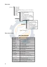
1. HDG SET

2. SPD MODE

MAN   LOG  NAV*

                                        LOG (S-BT)

                                        LOG (S-WT)

3. MAN SPD

4. SET & DRIFT

5. DISPLAY

6. MARK/LINE

7. TUNE

8. NAV DATA

9. EBL/VRM/+

0.

OTHERS

* NAV shown on R-type only.

Figure 9 OTHER menu

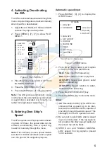
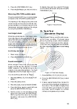
2. Press the [4] key twice to select SET/

DRIFT.

          SET & DRIFT 

1.

2. SET/DRIFT

OFF  ON

3.  SET 000.0

4.  DRIFT

0-19.9 KT

Figure 10 SET/DRIFT menu

3. Press the [2] key to select ON from the

SET DRIFT field, and then press the [EN-
TER/SELECT] key.

4. Press the [3] key twice, enter SET value,

and then press the [ENTER/SELECT]
key.

5. Press the [4] key twice, enter DRIFT

value, and then press the [ENTER/SE-
LECT] key.

6. Press the [MENU] key.

12. Alarms

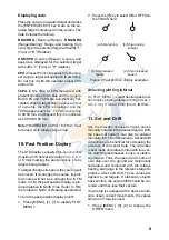
CPA/TCPA alarm

Visual and audible alarms are generated
when the predicted CPA and TCPA of any
target become less than their preset limits.
Press the [AUDIO OFF] key to acknowledge
and silence the CPA/TCPA audible alarm.

The ATA continuously monitors the predicted
range at the Closest Point of Approach (CPA)
and predicted time to CPA (TCPA) of each
tracked target to own ship.

When the predicted CPA of any target be-
comes smaller than a preset CPA alarm range
and its predicted TCPA less than a preset
TCPA alarm limit, the ATA releases an au-
dible alarm. In addition, the target plot sym-
bol changes to a triangle and flashes together
with its vector.

Provided that this feature is used correctly, it
will help prevent the risk of collision by alert-
ing you to threatening targets. It is important
that GAIN, A/C SEA, A/C RAIN and other
radar controls are properly adjusted and the
ATA is set up so that it can track targets ef-
fectively.

CPA/TCPA alarm ranges must be set up prop-
erly taking into consideration the size, ton-
nage, speed, turning performance and other
characteristics of own ship.

The CPA/TCPA alarm feature should never
be relied upon as a sole means for detecting
the risk of collision. The navigator is not re-
lieved of the responsibility to keep visual look-
out for avoiding collisions, whether or not the
radar or other plotting aid is in use.

Follow the steps shown below to set the CPA/
TCPA alarm ranges:

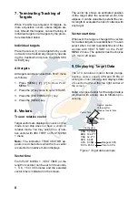
1. Press [MENU], [7], [7] to display PLOT

MENU 1.

2. Press [5] (CPA SET) to select CPA limit

desired from the CPA SET line.

3. Press the [ENTER/SELECT] key.

4. Press [6] (TCPA SET) to select a TCPA

limit desired.

www.reelschematic.com

www.reelschematic.com

Summary of Contents for ARP-17

Page 1: ...AUTOMATIC TRACKING AID MODEL ARP 17 www reelschematic com www reelschematic com...

Page 2: ...8 6 5 2 1 1 1 Te l e f a x 0 7 9 8 6 5 4 2 0 0 Yo u r L o c a l A g e n t D e a l e r A l l r i g h t s r e s e r v e d P U B N o O M E 3 0 4 6 0 A R P 1 7 D A M I F I R S T E D I T I O N N O V 1 9 9...

Page 3: ...nd crew The navigator has the responsibility to check all aids available to confirm position Electronic aids are not a substitute for basic navigational principles and common sense This auto plotter a...

Page 4: ...e ATA 5 5 Entering Own Ship s Speed 5 6 Acquiring Targets 6 7 Terminating Tracking of Targets 8 8 Vectors 8 9 Displaying Target Data 8 10 Past Position Display 9 11 Set and Drift 9 12 Alarms 10 13 Tra...

Page 5: ...g our purposes Thank you for considering and purchasing FURUNO Features The ATAARP 17 is an optional circuit board which is accommodated in the display unit of the FR 1500 MARK 3 Series Radars and the...

Page 6: ...PAs ATAs comply with these require ments OPERATIONAL OVERVIEW Acquisition and tracking A target which is hit by 5 consecutive radar pulses is detected as a radar echo Auto acquisition is not defined i...

Page 7: ...wn ship s course and speed The resulting true or relative vector is displayed for each of the tracked targets This process is up dated continually for each target on every scan of the radar Automatic...

Page 8: ...item selected ENTER SELECT key Registers selection displays data of target selected ACQ key Manually acquires target AUDIO OFF key Silences CPA TCPA alarm MENU key Opens closes menu CANCEL CLEAR key...

Page 9: ...P C s t e S T E S A P C T 6 e g n a r m r a l a A P C T s t e S K C A R T 7 f f o n o y a l p s i d n o i t i s o p t s a p s n r u T M R A L A O I D U A 8 f f o n o m r a l a o i d u a s n r u T L A...

Page 10: ...hrough the menu Note It is customary to use a speed relative to water for collision avoidance and a speed over the ground for navigation purpose Automatic speed input 1 Press MENU 0 0 to display the O...

Page 11: ...l miles from own ship 2 Place the cursor on the target 3 Press MENU 7 7 0 0 9 9 4 Place the cursor on the target and press the PLOT SYMBOL key ACQ key on the FR 1710 1725 1760DS 5 Press the MENU key T...

Page 12: ...he lower upper right edge of the area and press the ENTER SELECT key Sector 0 5nm A A B B Figure 6 Automatic acquisition area Note If you wish to create an auto acquisi tion area having a 360 degree c...

Page 13: ...U 1 VECT TIME or the length of vectors can be set to 30 seconds 1 3 6 15 or 30 minutes and the selected vector time is indicated on the screen The vector tip shows an estimated position of the target...

Page 14: ...e In TM the past position display is pro duced relative to North True Trails In RM it is relative to North or Heading as selected To turn the past position display on off 1 Press MENU 7 7 to display P...

Page 15: ...than a preset CPAalarm range and its predicted TCPA less than a preset TCPA alarm limit the ATA releases an au dible alarm In addition the target plot sym bol changes to a triangle and flashes togethe...

Page 16: ...xits the zone You can set the guard zone as follows 1 Press the MENU 7 7 to display PLOT MENU 1 2 Press the 0 key twice 3 Press the 3 key to select GUARD ZONE 4 Press the 3 key again to select SET and...

Page 17: ...at regular intervals or on operator demand 1 Press MENU 0 0 0 0 2 Press the 2 key twice to start the diag nosis sequence The results of the test appear as shown below FR 1500 M 3 Series Test 1 Progra...

Page 18: ...to select OFF REL or TRUE from the TTM field as appropriate 3 Press the ENTER SELECT key followed by the MENU key Target data contain as follows Target number Target distance from own ship Bearing fro...

Page 19: ...imum number of targets 10 Acquisition range 0 2 to 32 nm Tracking range 0 1 to 32 nm 3 Vector Vector length 30 sec 1 2 3 6 15 30 min Mode true velocity or relative velocity 4 History plotting interval...

Page 20: ...arm 11 L Lost target alarm 10 M Manual speed input 6 Menu tree 4 P Past position display 9 Plot symbol mark 7 S Set and drift 9 Ship s speed target based speed 6 Speed input automatic 5 manual 6 T Tar...

Reviews: