1-7
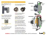
9. Connect the wires to the RF unit, referring to the illustration below.
RF unit
10. Attach the EMC core as shown below.
How to attach EMC core
11.Attach the shield covers. Make sure the cable is not caught by the cover and that the cover is
placed into the cover base groove before tightening screws.
12.Ensure there are no free-moving screws inside the radome. If there are, secure them in place
with tape or remove them. Remove all remaining loose gaskets. Failure to secure or remove
screws and gaskets may cause the equipment to malfunction or fail.
13.Attach the radome cover. Align the triangle mark on radome cover with that on radome base.
How to attach the radome cover
14.Fasten the radome bolts.
J802
J801
J611
MD-9208
03P9522
PTU-9335
Cable
entry
J802
J801
J611
MD-9208
IF-9214
PTU-9335
Cable
entry
Antenna unit: RSB-0071-057
XN10A-RSB-0070-064
XN10A-RSB-0073-064
XN12A-RSB-0070-059
XN12A-RSB-0073-059
Antenna unit: RSB-0071-057A
XN10A-RSB-0070-064A
XN10A-RSB-0073-064A
XN12A-RSB-0070-059A
XN12A-RSB-0073-059A
EMC Core installed correctly,
inside radome base and
above cable clamping plate.
Radome cover
Radome base
Summary of Contents for 1835
Page 2: ......
Page 24: ...1 18 This page is intentionally blank...
Page 41: ...Y Hatai D 1...
Page 42: ...8 Jul 09 R Esumi D 2...
Page 43: ...5 Feb 09 R Esumi D 3...
Page 44: ...5 Feb 09 R Esumi D 4...


