


3
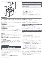
Product Overview
2
1
3
4
5
8
9
10
6
7
Item
Description
1
Induction Element
2
Ceramic Glass
3
Control Panel
4
Child Safety Lock Key
5
Timer Key
6
Digital Display
7
Power, Temp and Power Adjustment Keys
8
Temp. Mode Key
9
Heat Mode Key
10
ON/OFF Key
NOTE:
The illustration may look different from actual product.
Installation
This cooktop is not user serviceable. Installation must be completed by a
qualified technician.
WARNING
Do not store or use gasoline or other flammable vapors and liquids in the
vicinity of this or any other appliance.
To eliminate the risk of burns or fire due to overheating, cabinets located
above the induction cooktop can be protected by using a range hood.
Follow the range hood installation instructions and/or local codes when
installing the cabinetry around the induction cooktop.
NOTE:
All electric cooktops run off a single phase, three-wire cable,
120V/60Hz AC only electrical supply with ground. The installation should be
made using wires, conduits, and fittings size in accordance with the National
Electrical Code, ANSI/NFPA 70.
What’s in the Box
Make sure all the following items are included in the packaging. If any item is
damaged or missing, contact your dealer.
●
Induction Cooktop x 1
●
User Manual
●
Warranty Manual
Electrical Connection
Connect the cooktop to a 120V, 60Hz, AC only, 15A dedicated circuit. It is
recommended that a separate circuit serving only the cooktop be provided.
Countertop Use
The cooktop comes with 4 rubber feet attached to the bottom to prevent
sliding. It can be placed on a flat surface for countertop use.
Select an open area and place the cooktop on a dry, stable and level surface
where the plug will reach an electrical outlet.
Drop-in Use
Before Installing the Induction Cooktop
1.
Ensure that cooktop is turned off.
2. Visually inspect the cooktop for damage. Make sure all cooktop screws
are tightened.
Induction Cooktop Installation
1.
Cut an opening in the counter surface. Refer to the drawings on the
following pages for appropriate dimensions and follow these instructions:
- Select heat-resistant table material to avoid damage caused by heat
radiation.
- Ensure that the underside of the induction cooktop is well ventilated
and the air inlet is not blocked.
- The distance between the cooktop and any cupboard above the
cooktop should be at least 30" (762mm).
2. After cutting the opening, remove any shavings or other loose material that
may interfere with the appliance’s operation.
3. Place the cooktop into the countertop cutout.
4. Plug the power cord into the dedicated grounded electrical outlet.
NOTE:
- Do not seal the cooktop to the countertop. The cooktop may be
removed if service is necessary.
- For unframed installation, adhere foam strip to the outer edge of
the
glass.
- For installation into an RV, apply butyl tape instead of the supplied
foam tape. Butly tape will provide adequate adhesion and still allow for
removal if the unit needs to be serviced.
- The power cord is located on the top right side of the cooktop. Locate
the grounded electrical outlet in an accessible area reachable by the
cooktop power cord.
A
E
D
B
C
C
12½"(316mm)
15"(3
82m
m)
2⅝
"(68
mm
)
Distance to
combustible
materials
Dimensions
A
B
C
D
E
Min. 14" (355mm)
Max. 145/16" (365mm)
Min. 115/8"(295mm)
Max. 117/8"(303mm)
Min. 2"
(51mm)
Min. 2 1/2"
(64mm)
Min. 2"
(51mm)
NOTE:
Dimensions C and E are the distance to the combustible materials
from the edge of the cutout.
REV DATE: 10.14.2022 | CCD-0005585


