RVC-7W
- 6 -
ate to working with metal.
10. The RVC-7W’s brackets may now be in-
stalled. The “hooks” should be facing upwards
to support the rectangular cutouts in the rear of
the RVC-7W’s chassis.
11. For new construction remember that the
signal and AC wiring will mount through the
bottom surface of the RVC-7W’s chassis. Make
sure there’s suffi cient signal wire or cabling
to pass through the bottom of the RVC-7W,
through the front panel cutout, and ultimately
connecting to the fl at screen’s or projector’s
input panel. The A.C. wiring for the RVC-7W
typically requires less than 1ft. of wire beyond
the bottom of the chassis. However, a service
loop, or some slack is always a good idea, and
there will be plenty of space below the RVC-
7W’s chassis to store it.
12. For either retrofi t, or fi nal installation of new
construction, remove the RVC-7W from its car-
ton. Use a Phillips screwdriver to remove the
(5) front panel screws from the front panel.
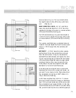
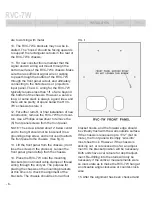
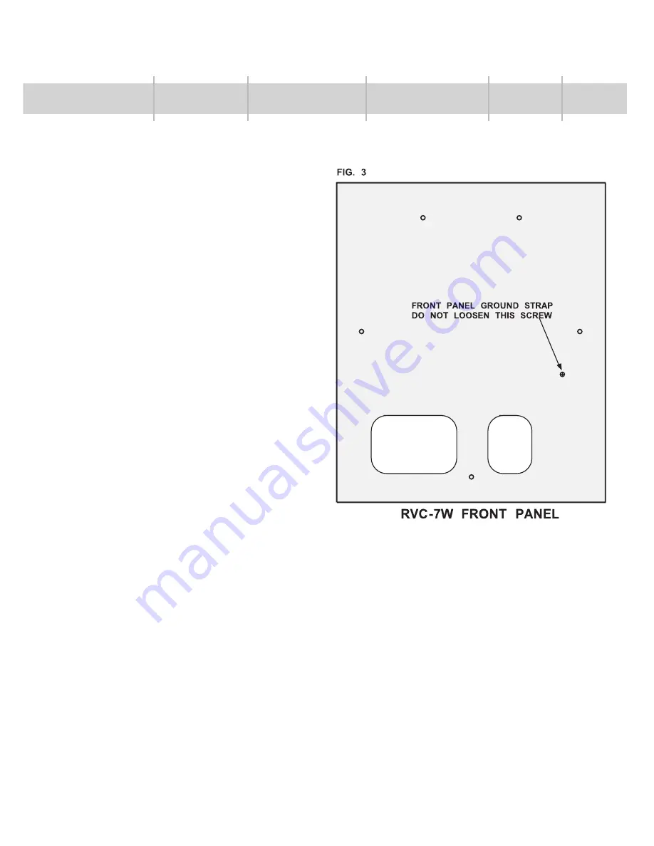
NOTE: The screw located about 2” below center
and to the right should not be loosened! It is a
grounding strap screw, and is not used to attach
the front panel to the chassis. (See fi g. 3)
13. Lift the front panel from the chassis, (don’t
lose the screws in the process). Loosen the
front panel ground strap from the chassis.
14. Place the RVC-7W onto the mounting
brackets (do not install cable clamps or thread
wiring through the unit yet. The purpose for
placing the chassis on the mounting brackets
at this time is to check the alignment of the
brackets. The chassis should rest on all four
bracket hooks, and the forward edge should
be virtually fl ush with the walls outside surface.
If the chassis is recessed up to 1/32” (but no
more), the front panel will simply “sink into”
most sheet rock. However, if the chassis is
sticking out, or is recessed too far, an adjust-
ment to the bracket position will be necessary.
Both units have oval cutouts for depth adjust-
ment. Re-drilling into the studs will only be
necessary if the vertical measurements were
so inaccurate as to make the RVC-7W hang at
a noticeable angle clockwise or counter-clock-
wise.
15. After the alignment has been checked and
INTRODUCTION
FEATURES
DESCRIPTION
INSTALLATION
SAFETY
SPECS


