34 Canyon View Drive Orinda, CA., 94563 p:925.253.2969 f:925.253.4894
SYNTH ON LED
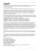
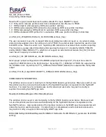
This LED is useful to determine overall board operation/configuration, as follows:
GREEN:
Board is powered but not configured
RED:
Board is configured using software profile selection (EXT_MOD=FALSE)
Mixed (yellow): Board is in EXTERNAL MODULATION mode and MODA input != MODB input
OFF:
Board is in EXTERNAL MODULATION mode and MODA input = MODB input
HARDWARE INSTALLATION AND SETUP
To avoid overheating, the SYNTH300 must be installed in a well-cooled workstation or server chassis,
or alternatively in an industrial chassis PC. Installation in a standard desktop PC without fans at the
front end of the card cage may cause the SYNTH300 to overheat, and resulting damage is not covered
by warranty.
1. Use the shutdown command on your system and then turn OFF the power to the system.
BEFORE REMOVING THE COMPUTER SYSTEM COVER OR REMOVING ANY BOARD, BE
SURE THAT THE POWER TO THE COMPUTER, AS WELL AS TO ALL PERIPHERAL DEVICES
IS OFF. WEAR A STATIC-DISSIPATING WRISTBAND WHICH IS GROUNDED TO THE SYSTEM
CHASSIS WHILE OPENING OR WORKING ON YOUR SYSTEM.
2. Remove any screws that attach the computer system cover and remove the cover.
3. Remove the filler bracket from the PCI bus slot into which you wish to install your SYNTH300 board.
If a mixture of 5V and 3.3V slots are available in the system, choose a 32-bit 5V slot as your first
preference. If that is not available, install it in a 32 or 64-bit 3.3V slot. For details, refer to the
hardware manual for your computer system.
4. Hold the SYNTH300 board by the top of the metal PCI bracket. Then hook the tab on the bottom
edge of the SYNTH300's metal bracket into the corresponding slot in the computer's rear panel.
Carefully push the SYNTH300 down so its PCI bus connector mates with the PCI bus connector on
the motherboard. Be sure that the SYNTH300 is seated firmly into the motherboard PCI bus
connector. Check that no other PCI boards have become unseated when the SYNTH300 was
installed, as motherboards may flex slightly when installing PCI boards.
5. Plug coaxial I/O cables for the analog outputs into the appropriate SMA connectors on the
SYNTH300's rear bracket at the rear of the system. Please refer to the diagram on page 8 of this
manual.
6. We recommend that synthesizer output channels A and B (the 1st and 2nd SMA connectors from
the bracket top) initially be connected to an oscilloscope set for 200mV/div., so you can observe the
two synthesized waveforms operation when running the example software.
7. Replace the computer system cover, installing all screws you had removed. Reconnect the power
cables to the system and peripherals.
8. Power up and reboot the system. The system will then be ready for software installation.
r1v06
Page
11
of
31
Copyright © 2008 – 2010 Furaxa Inc.


