


The camera may be damaged or destroyed if it is:
•
Not used for its intended purpose
•
Subjected to heavy knocks and vibrations
•
Used outside of its operating limits
•
Operated in a radioactive environment
•
Pointed towards a strong light source (sun) with its shutter open, regardless whether the camera is switched on
or off
•
Is not installed, maintained, configured or repaired by authorised, trained personnel
The camera housing warms up noticeably compared with its surroundings during operation. When installing the
camera in a system housing, ensure that heat is adequately dissipated into the system housing.
Always make sure that a lens is mounted or a dust cap is fitted to prevent the ingress of dust particles that might
become visible in the picture when the camera is put into service.
Commissioning
Before commissioning the FAC 960, mount the selected lens and use Config Tool to set the appropriate shutter type
and store it in the camera. In the case of signal-actuated shutters, for normal applications set the minimum shutter
time to 20 ms and perform shutter adjustment as required.
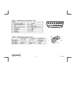
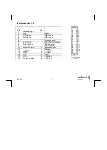
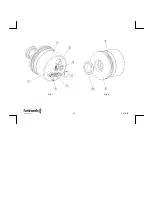
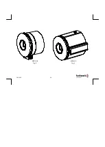
Connectors and controls Figure 1
All connectors and configuration controls are located at the rear of the camera housing (1).
The following components are provided:
(2)
FBAS video output BNC
(3)
System connector, 15-pin D-Sub connector
(4)
Plug connector for lens iris control (selection and adjustment, e.g. using Config Tool)
(5)
Cover for digital signal connector
(6)
Earthing screw for equipotential bonding of camera housing
27
FAC 960
Summary of Contents for FAC 960 IR
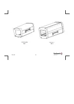
Page 5: ...Bild 1 Bild 2 5 FAC 960...
Page 18: ...ADP 930 MID 930 Bild 3 Bild 4 FAC 960 18...
Page 19: ...TUB 930 MIW 930 Bild 5 Bild 6 19 FAC 960...
Page 20: ...CW CWN 930 W WN 930 Bild 7 Bild 8 FAC 960 20...
Page 21: ...21 FAC 960...
Page 23: ...Fig 1 Fig 2 23 FAC 960...
Page 36: ...ADP 930 MID 930 Fig 3 Fig 4 FAC 960 36...
Page 37: ...TUB 930 MIW 930 Fig 5 Fig 6 37 FAC 960...
Page 38: ...CW CWN 930 W WN 930 Fig 7 Fig 8 FAC 960 38...
Page 39: ...FAC 960...